
This document introduces the PS21265-P/AP Intelligent Power Module by MITSUBISHI SEMICONDUCTOR, including its application, integrated power functions, and package outlines. The module is a 600V/20A low-loss 5th generation IGBT inverter bridge for three-phase DC-to-AC power conversion. It is designed for AC100V~200V three-phase inverter drive for small power motor control. The module features integrated drive, protection, and system control functions, including drive circuit, high voltage high-speed level shifting, control supply under-voltage protection for upper-leg IGBTs, and drive circuit, control supply under-voltage protection, short circuit protection for lower-leg IGBTs. It also provides fault signaling for SC and UV faults, and an input interface compatible with 3, 5V line. The module is UL Approved.
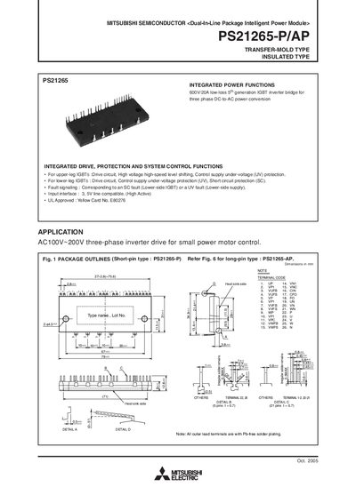
The Mitsubishi PS21265-P/AP is a dual‑in‑line package intelligent power module (IPM) designed for three‑phase inverter drives up to 600 V and 20 A. The manual provides integrated drive, protection and system control functions, including fault signaling, under‑voltage and short‑circuit protection.
The document includes maximum electrical ratings, thermal resistance data, mechanical characteristics, recommended operating conditions, timing charts for protective functions, wiring guidelines, and example application circuits to help engineers integrate the module safely and efficiently.
| Supply voltage (Veco) | 450 V |
|---|---|
| Collector‑emitter voltage (VCES) | 600 V |
| Collector current per IGBT | 20 A |
| Collector dissipation per chip | 51.2 W |
| Control supply voltage (VD) | 20 V |
| Isolation voltage | 2500 V rms (1 min, 60 Hz) |
| Weight | 54 g |
| Recommended mounting torque | 1.18 N·m |
Each IGBT can carry up to 20 A continuous collector current.
A torque of 1.18 N·m is recommended for the M4 mounting screw.
The module provides an isolation voltage of 2500 V rms for 1 minute at 60 Hz.