
Key facts
- Brand
- Linear Technology
- Model
- DC185
- Category
- demo board
- Industry
- Electronics
- Documents
- 2
- Languages
- EN · ZH
- Last added
- 2026-11-17
Start here
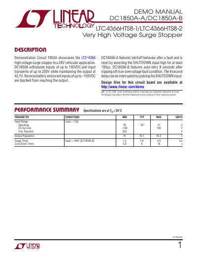
Linear Technology DC1850A-A/DC1850A-B High Voltage Surge Stopper Demonstration Circuit Manual
The DC1850A-A/DC1850A-B is a demonstration circuit for Linear Technology's LTC4366 high voltage surge stopper, designed for 28V vehicle applications. It withstands input voltages up to 100VDC and input transients up to 250V while maintaining a 43.1V output. The board includes protection against reverse battery and errant inputs up to -100VDC. The DC1850A-A features latchoff behavior after a fault, reset by asserting SHUTDOWN high for at least 100µs. The DC1850A-B features auto-retry 9 seconds after tripping off in an overvoltage fault condition, with the delay interruptible by pulsing SHUTDOWN.
The board layout provides 87mil clearance between input and output to prevent arcing. It includes ancillary circuits for shutdown level shifting, constant current LED driver, and reverse voltage protection. Operation is straightforward: connect an input supply of 18V to 41V and an output load of up to 1.5A. The SHUTDOWN turret defaults to ON if left open, and pulling it to 1.8V or higher causes shutdown. This manual is written in Chinese.
Linear Technology DC185 specifications
| Output voltage (J1 removed) | 11.6 / 12.0 / 12.4 V |
|---|---|
| Output voltage (J1 inserted) | 4.85 / 5.00 / 5.17 V |
| Maximum switch current | 6 / 8 / 10 A |
| Input voltage range | 2.7 to 12 V |
| Switching frequency | 440 to 580 kHz (typical 500 kHz) |
| Output ripple voltage | 80 mV P-P |
| Line regulation | 20 mV |
| Load regulation | 18 mV |
| S/D shutdown threshold | 0.6 to 2 V (typical 1.3 V) |
| S/D synchronization range | 600 to 800 kHz |
| Supply current | 100 µA typical |
| LT1370 input supply range | 2.7 to 30 V (DC185 maximum 12 V) |
| LT1370 quiescent current | 4.5 mA |
| LT1370 switch current | 6 A minimum |
| LT1370 switch on-resistance | 0.065 Ω typical |
| LT1370 switch breakdown voltage | 35 V minimum |
| LT1370 switching frequency | 500 kHz fixed |
| LT1370 shutdown supply current | 40 µA maximum |
| LT1370 reference voltage | 1.245 V |
| LT1370 negative feedback voltage | -2.48 V |
| LT1370 VC pin voltage | 1 V to 1.9 V |
| Inductor | 6.8 µH, 20% |
| Inductor saturation current | 5 A |
| Output voltage setting | VOUT = VREF (1 + R2/R1) |
Source: Linear Technology LT1370 DC/DC Step-Down Regulator Demonstration Board DC185 Demo Manual
All Linear Technology DC185 documents by type
Day-to-day operation, settings and troubleshooting. Start here if the product is already set up.
Questions answered in these manuals
What is the DC185 demonstration board intended for?
It is intended for evaluating the LT1370 switching regulator in a typical step-up application.
From: Linear Technology LT1370 DC/DC Step-Down Regulator Demonstration Board DC185 Demo Manual
How is the output voltage set on the LT1370?
The output voltage is set by R1 and R2, where VOUT = VREF (1 + R2/R1).
From: Linear Technology LT1370 DC/DC Step-Down Regulator Demonstration Board DC185 Demo Manual
What is the maximum input voltage the DC1850A can handle?
The DC1850A can handle input voltages up to 100VDC.
From: Linear Technology DC1850A-A/DC1850A-B High Voltage Surge Stopper Demonstration Circuit Manual
How does the DC1850A-B handle overvoltage faults?
The DC1850A-B features auto-retry 9 seconds after tripping off in an overvoltage fault condition, with the delay interruptible by pulsing SHUTDOWN.
From: Linear Technology DC1850A-A/DC1850A-B High Voltage Surge Stopper Demonstration Circuit Manual