
Key facts
- Brand
- Analog Devices
- Model
- ADL5513
- Industry
- Industrial
- Documents
- 2
- Languages
- EN
- Last added
- 2012-05-03
Start here
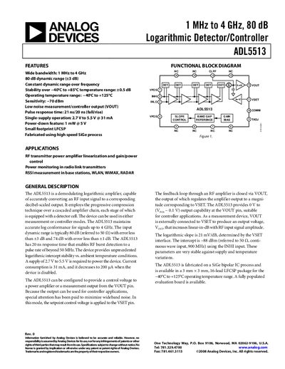
Analog Devices ADL5513 Product Handbook
The ADL5513 is a demodulating logarithmic amplifier that converts RF input signals to a decibel‑scaled output. It can be used in measurement or controller modes for applications such as RF transmitter power‑amplifier linearization, power monitoring, and RSSI measurement in base stations, WLAN, WiMAX and radar systems.
Key features include a 1 MHz‑to‑4 GHz bandwidth, 80 dB dynamic range, 2.7 V‑to‑5.5 V single‑supply operation, 21 ns pulse response time, and a logarithmic slope of 21 mV/dB. Detailed specifications, pin descriptions, absolute maximum ratings, and calibration procedures are provided.
Analog Devices ADL5513 specifications
| Bandwidth | 1 MHz to 4 GHz |
|---|---|
| Dynamic range (typical) | 80 dB |
| Supply voltage | 2.7 V to 5.5 V |
| Pulse response time | 21 ns fall, 20 ns rise |
| Logarithmic slope | 21 mV/dB |
| Input impedance | 1.3 kΩ/0.4 kΩ pF |
| Operating temperature range | –40 °C to +125 °C |
All Analog Devices ADL5513 documents by type
Ratings, dimensions and ordering codes, for selection and design work.
Questions answered in these manuals
What supply voltage range does the ADL5513 require?
The device operates from a single supply of 2.7 V to 5.5 V.
What is the pulse response time of the ADL5513?
The pulse response time is 21 ns for the fall edge and 20 ns for the rise edge.
What is the supply voltage range for the ADL5513?
The device operates from 2.7 V to 5.5 V.
From: Analog Devices ADL5513 Logarithmic Detector/Controller Datasheet
What is the pulse response time of the ADL5513?
The pulse response time is 21 ns fall and 20 ns rise.
From: Analog Devices ADL5513 Logarithmic Detector/Controller Datasheet