
Key facts
- Brand
- Toshiba
- Model
- VF-S11
- Documents
- 5
- Languages
- PT · JA · ZH
- Last added
- 2012-05-03
Start here
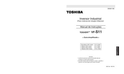
Toshiba VF-S11 Industrial Inverter User Manual
This manual covers essential safety precautions for the VF‑S11 inverter, including warnings against opening the front panel, handling high‑voltage components, and operating the unit in wet or hazardous environments. It also details the required checks before use and the procedures for disconnecting power safely.
Installation instructions describe mounting the inverter on a flat metal plate in a well‑ventilated area, maintaining minimum spacing between units, and ensuring proper ventilation. The document includes wiring diagrams for both negative‑sink and positive‑source logic, terminal descriptions, and recommended cable sizes for various power ratings. This manual is written in Portuguese.
Toshiba VF-S11 specifications
| Power rating (monofásico 240 V) | 0.2 kW – 2.2 kW |
|---|---|
| Power rating (trifásico 240 V) | 0.4 kW – 15 kW |
| Power rating (trifásico 500 V) | 0.4 kW – 15 kW |
All Toshiba VF-S11 documents by type
Day-to-day operation, settings and troubleshooting. Start here if the product is already set up.
Mounting, wiring and first power-up. Read it before the hardware goes in.
Questions answered in these manuals
What safety precautions must be observed before operating the inverter?
Do not disassemble, modify, or repair the inverter; always disconnect power before handling; keep the front panel closed while powered; avoid contact with high‑voltage parts and liquids.
What are the available wiring logic options for the VF‑S11?
The inverter supports two wiring configurations: negative‑sink (common CC) and positive‑source (common P24) logic, each with its own standard connection diagram.
What is the maximum operating temperature of the VF‑S11?
The VF‑S11 can operate up to 60 °C.
How should the inverter be installed to ensure proper cooling?
Install the inverter in a well‑ventilated indoor area, mount it on a flat metal plate, keep adequate spacing between units, and remove the top ventilation covers when installing side‑by‑side.
What standard connection diagrams are provided in the manual?
The manual includes two standard wiring diagrams: one using negative logic (SINK) and another using positive logic (SOURCE).
Can the VF‑S11 be used with three‑phase induction motors?
Yes, it is intended for general industrial three‑phase induction motor speed control.