
Key facts
- Brand
- Analog Devices
- Model
- AD6642
- Documents
- 2
- Languages
- EN
- Last added
- 2023-11-24
Start here
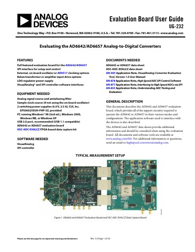
Analog Devices AD6642/AD6657 Evaluation Board User Guide
This document provides detailed instructions for using the AD6642/AD6657 evaluation board, including hardware configuration, power supplies, input/output signals, and jumper settings. It also describes the required software tools and documentation for testing and evaluating the ADCs. The board supports both dual-channel (AD6642) and quad-channel (AD6657) operation with various input and clocking options.
Read onlineAnalog Devices AD6642 specifications
| Input Drive Level | 10 dBm to achieve 2 V p-p full scale into 50 Ω |
|---|---|
| Clock Input | 50 Ω terminated, ac-coupled, single-ended sine wave input |
| Supported ADCs | AD6642 and AD6657 |
Source: Analog Devices AD6642/AD6657 Evaluation Board User Guide
All Analog Devices AD6642 documents by type
Day-to-day operation, settings and troubleshooting. Start here if the product is already set up.
Ratings, dimensions and ordering codes, for selection and design work.
Questions answered in these manuals
What software is needed to use the evaluation board?
VisualAnalog SPI controller software is required to interface with the ADCs.
From: Analog Devices AD6642/AD6657 Evaluation Board User Guide
What are the default input settings for the evaluation board?
The A and B channel inputs are set up for a double balun-coupled analog input with 50 Ω impedance.
From: Analog Devices AD6642/AD6657 Evaluation Board User Guide
What is the maximum sampling rate of the AD6642?
The AD6642 can sample at up to 200 MSPS per channel, with typical operation at 185 MSPS.
From: Analog Devices AD6642 Dual IF Receiver Datasheet Rev A
What supply voltages does the AD6642 require?
Both the analog and digital sections run from a 1.8 V supply (AVDD and DRVDD).
From: Analog Devices AD6642 Dual IF Receiver Datasheet Rev A