
Key facts
- Brand
- Texas Instruments
- Model
- TVP7001
- Documents
- 2
- Languages
- EN
- Last added
- 2012-03-28
Start here
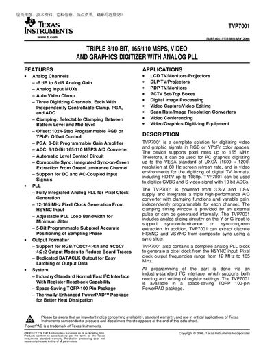
Texas Instruments TVP7001 Video Digitizer Data Sheet
The TVP7001 is a complete solution for digitizing video and graphics signals in RGB or YPbPr color spaces. It supports pixel rates up to 165 MHz and can handle PC graphics up to UXGA (1600 × 1200) at 60 Hz, as well as HDTV formats up to 1080p. The device integrates three high‑performance A/D converters, programmable gain amplifiers, and an analog PLL for pixel‑clock generation.
The part is supplied in a 100‑pin TQFP PowerPAD package (PZP) and is powered from 3.3 V and 1.8 V supplies. All programming is performed via a standard I²C interface, and the datasheet provides detailed electrical characteristics, pin assignments, and mechanical dimensions for board designers.
Texas Instruments TVP7001 specifications
| Pixel Clock Generation Range | 12 MHz – 165 MHz |
|---|---|
| ADC Resolution and Sample Rate | 8/10‑bit, 165/110 MSPS |
| Supply Voltages | IOVDD = 3.3 V, DVDD = 1.8 V, PLL_A18VDD = 1.9 V, A18VDD = 1.9 V, A33VDD = 3.3 V |
| Analog Input Voltage Range | 0.5 V – 2.0 Vpp |
| Package | 100‑pin TQFP PowerPAD (PZP) |
Source: Texas Instruments TVP7001 Video Digitizer Data Sheet
All Texas Instruments TVP7001 documents by type
Ratings, dimensions and ordering codes, for selection and design work.
Questions answered in these manuals
What is the maximum pixel clock frequency of the TVP7001?
The TVP7001 can generate a pixel clock up to 165 MHz.
What supply voltages are required for the TVP7001?
The device uses 3.3 V for IOVDD, 1.8 V for DVDD, and 1.9 V for the PLL and analog supplies (A18VDD, PLL_A18VDD, A33VDD).
What is the supply voltage range for the TVP7001?
The device uses a 3.3 V IOVDD supply and a 1.8 V DVDD supply.
What are the recommended coupling components for unused analog inputs?
Unused analog inputs should be grounded with a 10 nF capacitor, and the recommended coupling capacitor for active inputs is 0.1 µF.