
Key facts
- Brand
- Intersil
- Model
- ISL6729
- Industry
- Industrial
- Documents
- 2
- Languages
- EN
- Last added
- 2012-05-07
Start here
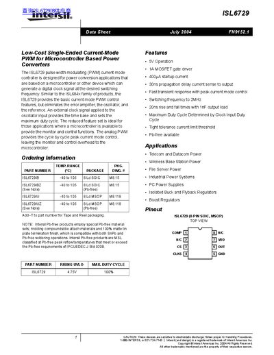
Intersil ISL6729 PWM Current-Mode Controller Data Sheet
The ISL6729 is a low‑cost, single‑ended current‑mode PWM controller intended for microcontroller‑based power converters. It requires an external clock signal for timing and provides a 5 V operation, 1 A MOSFET gate driver, and fast transient response.
The device operates from –40 °C to 105 °C, supports supply voltages of 4.75 V–5.25 V, and can handle clock frequencies up to 2 MHz with a maximum duty cycle of 99 %. It is offered in SOIC and MSOP packages and is Pb‑free compliant.
Intersil ISL6729 specifications
| Maximum Clock Frequency | 2 MHz |
|---|---|
| Maximum Duty Cycle | 99 % |
| Maximum Junction Temperature | 150 °C |
| Propagation Delay (Current Sense to Output) | 30 ns |
| Startup Current | 400 A |
Source: Intersil ISL6729 PWM Current-Mode Controller Data Sheet
All Intersil ISL6729 documents by type
Ratings, dimensions and ordering codes, for selection and design work.
Questions answered in these manuals
What is the maximum clock frequency the device can handle?
It can accept clock frequencies up to 2 MHz.
From: Intersil ISL6729 PWM Current-Mode Controller Data Sheet
What is the maximum duty cycle achievable with the ISL6729?
The maximum duty cycle is 99 %, set by the clock input duty cycle.
From: Intersil ISL6729 PWM Current-Mode Controller Data Sheet
How is the duty cycle set on the ISL6729?
The duty cycle is determined by the duty cycle of the external clock signal applied to the CLK pin.