
The ISL6729 is a single-ended current mode PWM controller from ISL company. It is designed for power conversion applications based on a microcontroller or other device that can generate a digital clock signal at the desired switching frequency. The device has 5V operating voltage, 1A MOSFET drive capability, 400µA startup current, 30ns propagation delay current sense to output, fast transient response, 2MHz switching frequency, 1nF output load 20ns rise and fall times, maximum duty cycle determined by clock input duty cycle, tight tolerance current limit threshold and other features.
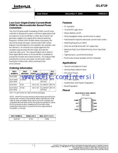
The ISL6729 is a low‑cost single‑ended current‑mode PWM controller intended for power‑conversion applications that use a microcontroller or other digital clock source. It omits the internal error amplifier, oscillator, and reference, relying on an external clock to set the switching frequency and maximum duty cycle.
Key features include 5 V operation, a 1 A MOSFET gate driver, 400 A startup current, fast transient response, and support for switching frequencies up to 2 MHz. Typical applications are telecom, datacom, wireless base‑station, and file‑server power supplies, as well as isolated buck, boost, and flyback regulators.
| Maximum Duty Cycle | 99 % |
|---|---|
| Minimum Duty Cycle | 0 % |
| Input High Voltage Level (VIH) | 2.8 V |
| Input Low Voltage Level (VIL) | 2.7 V |
| Undervoltage Lockout Start Threshold (typical) | 4.50 V |
The duty cycle is determined by the duty cycle of the external clock signal applied to the CLK pin.