
Key facts
- Brand
- STMicroelectronics
- Model
- L6585DE
- Industry
- Industrial
- Documents
- 5
- Languages
- EN
- Last added
- 2012-08-09
Start here
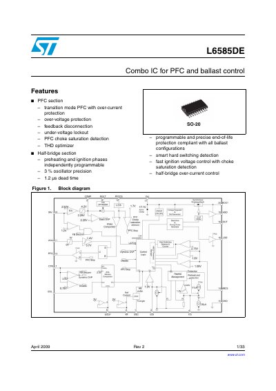
STMicroelectronics L6585DE Combo IC for PFC and Ballast Control Datasheet
The L6585DE is a combo IC for PFC and ballast control in an SO-20 package. Its PFC section uses transition-mode operation and includes over-current protection, over-voltage protection, feedback disconnection, under-voltage lockout, PFC choke saturation detection, and a THD optimizer.
The half-bridge section provides independently programmable preheating and ignition phases, 3% oscillator precision, 1.2 µs dead time, end-of-life protection, smart hard switching detection, and half-bridge over-current control. The datasheet covers pin functions, maximum ratings, electrical characteristics, application information, package mechanical data, and ordering information.
STMicroelectronics L6585DE specifications
| Product type | Combo IC for PFC and ballast control |
|---|---|
| Package | SO-20 |
| Oscillator precision | ±3% |
| Dead time | 1.2 µs |
| Maximum operating frequency | 250 kHz |
| Power dissipation at TA = 70 °C | 0.83 W |
| Junction operating temperature range | -40 to 150 °C |
| Operating supply voltage range | 11 to 16 V |
| PFC gate driver peak current | 300 mA source and 600 mA sink |
Source: STMicroelectronics L6585DE Combo IC for PFC and Ballast Control Datasheet
All STMicroelectronics L6585DE documents by type
Ratings, dimensions and ordering codes, for selection and design work.
How to use the product for one specific task, with worked examples.
Questions answered in these manuals
What is the L6585DE?
The L6585DE is a combo IC for PFC and ballast control.
From: STMicroelectronics L6585DE Combo IC for PFC and Ballast Control Datasheet
What package is the L6585DE available in?
It is available in an SO-20 package.
From: STMicroelectronics L6585DE Combo IC for PFC and Ballast Control Datasheet
What is the output voltage and current rating of this demonstration board?
The board provides an output of 48 V at 2.08 A.
From: ST STEVAL-ILL038V1 LED resonant driver demonstration board based on the L6585DE handbook
What is the acceptable input mains voltage range for this device?
The board accepts an input range of 90 to 265 VAC.
From: ST STEVAL-ILL038V1 LED resonant driver demonstration board based on the L6585DE handbook
What is the STEVAL-ILB005V2 demonstration board used for?
It serves as a demonstration board for the L6585DE combo IC, which handles power factor correction and ballast control.
From: ST STEVAL-ILB005V2 Demonstration board for the L6585DE combo IC for PFC ballast control handbook
What is the maximum ignition voltage for this board?
The maximum ignition voltage is 900 Vpk.
From: ST STEVAL-ILB005V2 Demonstration board for the L6585DE combo IC for PFC ballast control handbook