
Key facts
- Brand
- Torex
- Model
- XC9504 Series
- Category
- Other Electronics
- Industry
- Electronics
- Documents
- 2
- Languages
- EN
- Last added
- 2012-05-10
Start here
Torex XC9504 Series Dual DC/DC Controller Datasheet
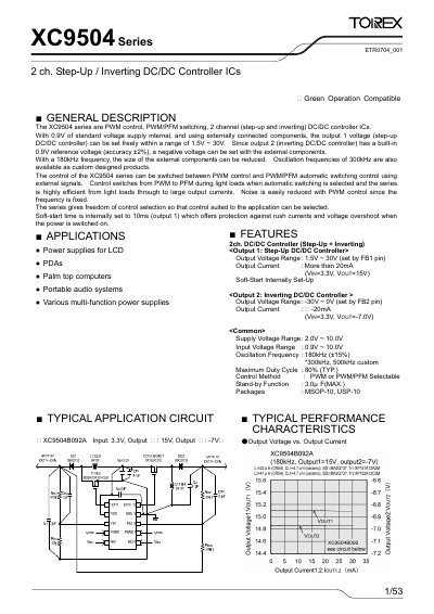
The XC9504 series are dual‑channel DC/DC controller ICs that provide a step‑up (boost) converter on channel 1 and an inverting converter on channel 2. They support PWM control, PWM/PFM automatic switching, and include built‑in soft‑start and standby functions.
The document lists pin assignments, absolute maximum ratings, electrical characteristics, typical application circuits, and design equations for setting output voltages. It also provides recommended external components and layout notes for optimal performance.
Torex XC9504 Series specifications
| Output Voltage Range (Channel 1) | 1.5 V ~ 30 V |
|---|---|
| Output Current (Channel 1) | > 20 mA |
| Supply Voltage Range | 2.0 V ~ 10.0 V |
| Oscillation Frequency | 180 kHz (±15%) |
| Maximum Duty Cycle | 80 % (typ.) |
| Package Types | MSOP‑10, USP‑10 |
All Torex XC9504 Series documents by type
Ratings, dimensions and ordering codes, for selection and design work.
Questions answered in these manuals
What is the typical oscillation frequency of the XC9504?
The typical oscillation frequency is 180 kHz with a tolerance of ±15 %.
How many channels does the XC9504 series have?
The XC9504 series has two channels: a step‑up (boost) controller and an inverting controller.
What is the output voltage range for channel 1?
Channel 1 can be set to any voltage between 1.5 V and 30 V.
From: Torex XC9504 Series 2-Channel Step-Up / Inverting DC/DC Controller IC Datasheet
How can the control mode be changed between PWM and PWM/PFM?
The control mode is switched by external signals on the PWM pins; a voltage below 0.2 V selects PWM/PFM automatic switching, while a voltage above 0.65 V selects PWM control.
From: Torex XC9504 Series 2-Channel Step-Up / Inverting DC/DC Controller IC Datasheet