
Key facts
- Brand
- Analog Devices
- Model
- ADUC832
- Industry
- Industrial
- Documents
- 11
- Languages
- EN
- Last added
- 2012-08-03
Start here
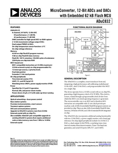
Analog Devices ADuC832 Product Handbook
The ADuC832 is a 12‑bit microcontroller with integrated ADC, dual DACs, flash memory, and a range of on‑chip peripherals. It operates from 3 V or 5 V and includes a PLL‑generated 16.78 MHz core clock, power‑down mode with 25 pA consumption, and extensive serial interfaces.
The handbook covers functional block diagrams, detailed pin configurations, timing specifications, memory organization, and programming information. It also includes application notes for optical networking, precision instrumentation, and sensor integration, as well as hardware design considerations such as power supply monitoring and watchdog timer usage.
Analog Devices ADUC832 specifications
| Program Flash Memory | 62kB |
|---|---|
| On Chip RAM | 2kB |
| Data Flash Memory | 4kB |
| Watchdog Clock Source | 32.768kHz external crystal |
| PLL Lock Indicator | PLLCON.6 |
All Analog Devices ADUC832 documents by type
Day-to-day operation, settings and troubleshooting. Start here if the product is already set up.
Ratings, dimensions and ordering codes, for selection and design work.
How to use the product for one specific task, with worked examples.
- Analog Devices ADuC832 Migration Guide from ADuC812 3 p
- AN-643 Closed-Loop Control Circuit Implementation of the ADuC832 and AD8305 in a Digital Variable Optical Attenuator 4 p
- Analog Devices ADuC831/832 DMA to XRAM Technical Note 5 p
- Analog Devices MicroConverter Time Interval Counter Application Note 4 p
Questions answered in these manuals
Does the ADC clock issue affect performance?
No, the document states that this issue does not affect the performance of the ADC.
From: ANALOG DEVICES ADuC832: Errata Sheet (Rev B1 2002-11-01-)
How many ADC clocks are required for a conversion in pipelined mode at voltages below 3.5V?
The number of ADC clocks can vary between 15 and 16 ADC clocks.
From: ANALOG DEVICES ADuC832: Errata Sheet (Rev B1 2002-11-01-)
What are the additional features of the ADuC832 compared to the ADuC812?
The ADuC832 includes 62kB program flash, 2kB on chip RAM, and 4kB data flash.
How does the ADC clock divider ratio change in the ADuC832?
The ADC Clock divider ratios are now 8, 4, 16, and 32.
What is the maximum optical signal attenuation level supported by this DVOA?
The system is designed to attenuate optical signals up to 40 dB.
What voltage range must be applied to the control input to set the VOA attenuation?
The attenuation value is set using an analog control voltage in the range of 5 V to 26 V.