
AN-643 Closed-Loop Control Circuit Implementation of the ADuC832 and AD8305 in a Digital Variable Optical Attenuator

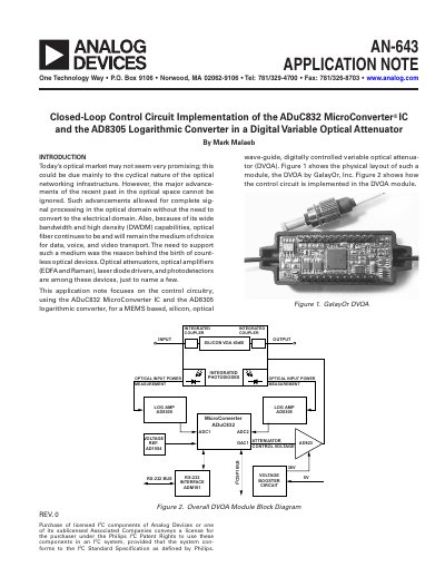
This application note focuses on the control circuitry, using the ADuC832 MicroConverter IC and the AD8305 logarithmic converter, for a MEMS based, silicon, optical Closed-Loop Control Circuit Implementation of the ADuC832 MicroConverter® IC and the AD8305 Logarithmic Converter in a Digital Variable Optical Attenuator.

AN-643 Closed-Loop Control Circuit Implementation of the ADuC832 and AD8305 in a Digital Variable Optical Attenuator - cover page
Brand
Analog Devices
Document type
Application Note
Language
English
Pages
4
File format
PDF
File size
395 KB
Published
03 August, 2012
Updated
28 September, 2023
MD5 checksum
0BEB98720163DF09A03C3BB5601BB0C5

About this manual

The document details the design of a control circuit for a Digital Variable Optical Attenuator (DVOA) capable of attenuating optical signals up to 40 dB. The system utilizes integrated photodiodes and Analog Devices components, specifically the ADuC832 MicroConverter IC and the AD8305 logarithmic amplifier, to measure input and output power levels.

What's inside

  • Introduction
  • System Functional Description
  • ADuC832 MicroConverter IC
  • AD8305 Logarithmic Amp

Frequently asked questions

What is the maximum optical signal attenuation level supported by this DVOA?

The system is designed to attenuate optical signals up to 40 dB.

What voltage range must be applied to the control input to set the VOA attenuation?

The attenuation value is set using an analog control voltage in the range of 5 V to 26 V.

How does changing the control voltage affect the amount of optical signal attenuation?

Increasing the voltage level results in increased attenuation.

Download PDF (395 KB)

More Analog Devices Manuals


View all Analog Devices manuals →