
Key facts
- Brand
- Hitachi
- Model
- L100-M
- Category
- Industrial Supply
- Documents
- 2
- Languages
- EN
- Last added
- 2023-10-17
Start here
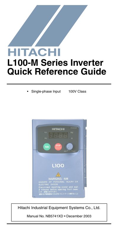
Hitachi L100-M Series Inverter Quick Reference Guide
This document serves as a quick reference guide for experienced users maintaining existing installations of the Hitachi L100-M Series Inverter. It provides essential information regarding power circuit terminals, control circuit terminal descriptions, and related technical parameters. The guide is intended for reference use only and directs users to the main L100 Inverter Manual for initial installation instructions and safety warnings.
Read onlineHitachi L100-M specifications
| Logic Input Supply | 24VDC supply, 30 mA max. |
|---|---|
| Logic Input Voltage | 27VDC max. |
| Logic Output Current | 50 mA max. ON current |
| Analog Input Voltage Range | 0 to 9.6 VDC |
| Analog Output Voltage Range | 0 to 10VDC |
| Relay Contact Rating (Resistive) | 250V AC, 2.5A |
| Over-current Trip Threshold | 200% of rated current |
Source: Hitachi L100-M Series Inverter Quick Reference Guide
All Hitachi L100-M documents by type
The shortest path to a working setup, usually only a few pages.
Questions answered in these manuals
What is the purpose of this guide?
This guide is intended for reference use by experienced users in servicing existing installations.
What should I do if the inverter trips on an error?
Press the Stop/Reset key to reset the inverter and clear the error.
What does the Run/Stop LED indicate?
The Run/Stop LED is ON when the inverter output is ON and the motor is developing torque, and OFF when the inverter output is OFF.
How is the potentiometer enabled for speed control?
The Potentiometer Enable LED turns ON when the potentiometer is enabled for value entry, allowing the operator to set motor speed.