
This document is a Hitachi L100-M series inverter quick reference guide that introduces the inverter's wiring method, control circuit and communication interface information.
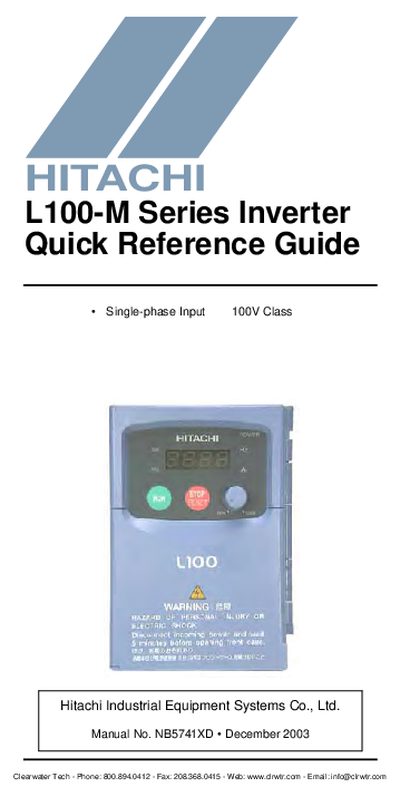
The Quick Reference Guide is intended for experienced users servicing existing Hitachi L100-M inverter installations. It includes safety warnings, power and control circuit terminal listings, and basic wiring diagrams for connecting the inverter to a motor and optional signal inputs.\n\nThe document details keypad operation, LED indicators, relay contact ratings, analog and PWM output specifications, and provides intelligent input and output terminal listings for configuring the inverter's functions.
| Logic input supply voltage | +24 VDC |
|---|---|
| Analog input current range | 4 to 19.6 mA (20 mA nominal) |
| PWM output voltage | 0 to 10 VDC, 1 mA max, 50% duty cycle |
The Run/Stop LED is ON when the inverter output is ON and the motor is developing torque, and OFF when the inverter output is OFF.
The Potentiometer Enable LED turns ON when the potentiometer is enabled for value entry, allowing the operator to set motor speed.