
Key facts
- Brand
- Hitachi
- Model
- 2SA1082
- Industry
- Industrial
- Documents
- 2
- Languages
- EN
- Last added
- 2012-06-01
Start here
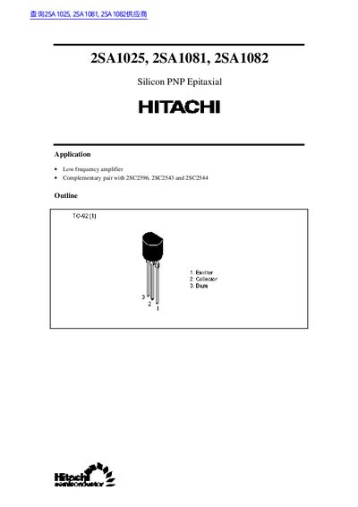
Hitachi 2SA1025, 2SA1081, 2SA1082 Datasheet
The 2SA1025, 2SA1081, and 2SA1082 are silicon PNP epitaxial transistors intended for low‑frequency amplifier applications and can be used as complementary pairs with other Hitachi devices. The document lists their pin outline and typical application notes.
Detailed absolute maximum ratings, electrical characteristics, and power‑dissipation curves are provided, along with legal and safety notices for proper use of these semiconductor products.
Hitachi 2SA1082 specifications
| Collector to base voltage (V_CBO) | -60 V (2SA1025), -90 V (2SA1081), -120 V (2SA1082) |
|---|---|
| Collector to emitter voltage (V_CEO) | -60 V (2SA1025), -90 V (2SA1081), -120 V (2SA1082) |
| Collector power dissipation | 400 mW for all models |
| Junction temperature (Tj) | 150 °C for all models |
| Storage temperature (Tstg) | -55 °C to +150 °C for all models |
| DC current transfer ratio (hFE) | 250 – 800 for all models |
| Gain‑bandwidth product (fT) | 9 MHz for all models |
| Collector‑output capacitance (Cob) | 35 pF for all models |
All Hitachi 2SA1082 documents by type
Ratings, dimensions and ordering codes, for selection and design work.
Questions answered in these manuals
What are the maximum collector‑to‑base voltage ratings for the transistors?
The 2SA1025 is rated at -60 V, the 2SA1081 at -90 V, and the 2SA1082 at -120 V.
How much power can each transistor dissipate safely?
Each device can dissipate up to 400 mW of collector power.
What applications are these transistors suited for?
They are intended for low‑frequency amplifier circuits and can be used as complementary pairs with 2SC2396, 2SC2543 and 2SC2544.
What are the absolute maximum collector‑to‑emitter voltages?
The maximum collector‑to‑emitter voltage is –60 V for 2SA1025, –90 V for 2SA1081, and –120 V for 2SA1082.