
Key facts
- Brand
- Maxim
- Model
- MAX713
- Industry
- Industrial
- Documents
- 3
- Languages
- EN
- Last added
- 2012-04-05
Start here
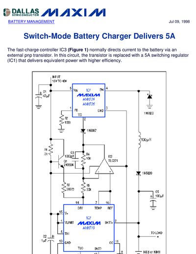
Maxim MAX713 5A Switch-Mode Battery Charger Application Note
The note explains a fast‑charge controller circuit where the external PNP transistor is replaced by a 5 A buck switching regulator (IC1). By controlling the PWM duty cycle of IC1, the controller IC3 regulates the charging current efficiently for battery packs.
Key design considerations include current sensing with R6, loop stability set by C4 at the CC terminal, and the effect of the battery filter capacitor C5 on the dominant pole. The document also references the MAX713 QuickView data sheet for further details.
Maxim MAX713 specifications
| Maximum charge rate | up to 4C |
|---|---|
| Number of series cells supported | 1 to 16 |
| Shunt regulator output voltage | +5 V |
| Idle current draw (no charging) | 5.4 mA |
| Operating temperature range (DIP version) | 0 °C to +70 °C |
Source: Maxim Integrated MAX712/MAX713 Fast-Charge Controller Datasheet
All Maxim MAX713 documents by type
How to use the product for one specific task, with worked examples.
Ratings, dimensions and ordering codes, for selection and design work.
Questions answered in these manuals
What external components are required for the MAX712/MAX713?
An external power PNP transistor, a blocking diode, three resistors, and three capacitors are the only required external components.
From: Maxim Integrated MAX712/MAX713 Fast-Charge Controller Datasheet
How many cells can be charged with the MAX712/MAX713?
The devices can charge between 1 and 16 series cells.
From: Maxim Integrated MAX712/MAX713 Fast-Charge Controller Datasheet
How many series cells can the MAX712/MAX713 charge?
They can charge from 1 up to 16 series cells.
What external components are required for a basic circuit?
Only an external power PNP transistor, a blocking diode, three resistors, and three capacitors are needed.