
Key facts
- Brand
- Honeywell
- Model
- GT1
- Documents
- 4
- Languages
- EN · JA · ZH
- Last added
- 2012-05-08
Start here
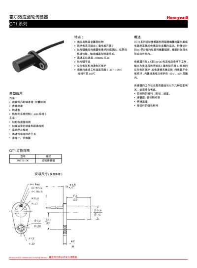
Honeywell GT1 Series Hall Effect Gear Sensor User Manual
The GT1 series Hall effect gear sensor uses an integrated circuit to provide a digital output based on magnetic field detection. It operates from 4.5 V to 24 VDC and outputs a digital signal, with built‑in reverse polarity protection (+60 V / –40 V) to prevent damage.
The manual lists technical specifications such as supply voltage, output current, temperature range, leakage current, and mechanical dimensions. It also includes reference tables for sensor placement, mounting dimensions, and contact information for technical support. This manual is written in Japanese.
Honeywell GT1 specifications
| Supply Voltage | 4.5 to 24 VDC |
|---|---|
| Supply Current | 10 mA typ., 20 mA max. |
| Output Type | Digital current sinking (open collector) |
| Switching Time Rise | 15 µsec max. |
| Switching Time Fall | 1.0 µsec max. |
| Operating Temperature Range | -40 °C to 150 °C |
All Honeywell GT1 documents by type
Day-to-day operation, settings and troubleshooting. Start here if the product is already set up.
Ratings, dimensions and ordering codes, for selection and design work.
Questions answered in these manuals
What supply voltage range does the GT1 sensor require?
It operates from 4.5 to 24 VDC.
What type of output does the GT1 sensor provide?
It provides a digital current sinking (open collector) output.
What supply voltage does the GT1 sensor require?
The sensor operates from 4.5 V to 24 VDC.
From: Honeywell GT1 Series Hall Effect Gear Sensor User Manual
What temperature range can the sensor operate in?
The sensor works from –40 °C to +150 °C.
From: Honeywell GT1 Series Hall Effect Gear Sensor User Manual
What supply voltage does the GT1 series sensor require?
The sensor operates from 4.5 V to 24 V DC.
What is the operating temperature range of the sensor?
It can operate from –40 °C up to 150 °C.