
Key facts
- Brand
- NXP
- Model
- UBA3070
- Documents
- 2
- Languages
- EN
- Last added
- 2023-10-27
Start here
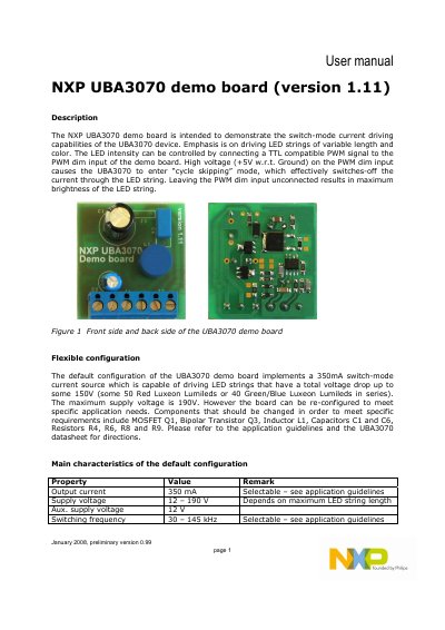
NXP UBA3070 demo board (version 1.11) User Manual
This document provides instructions for using the NXP UBA3070 demo board to demonstrate switch-mode current driving for LED strings. It includes circuit diagrams, PCB layouts, and a bill of materials. The board can be reconfigured using specific components like MOSFET Q1 and inductor L1 to meet application needs.
The default configuration delivers 350mA output current and supports LED strings with a total voltage drop up to 150V, with a maximum supply voltage of 190V. LED brightness is controlled via a TTL-compatible PWM signal on the PWM dim input, which can enter 'cycle skipping' mode to turn off current.
NXP UBA3070 specifications
| Output current | 350 mA |
|---|---|
| Supply voltage | 12 – 190 V |
| Aux. supply voltage | 12 V |
| Switching frequency | 30 – 145 kHz |
All NXP UBA3070 documents by type
Day-to-day operation, settings and troubleshooting. Start here if the product is already set up.
Ratings, dimensions and ordering codes, for selection and design work.
Questions answered in these manuals
How is LED brightness controlled on the demo board?
LED intensity is controlled by connecting a TTL-compatible PWM signal to the PWM dim input. High voltage (+5V) causes the UBA3070 to enter 'cycle skipping' mode, effectively switching off current.
What is the maximum supply voltage for the board?
The maximum supply voltage is 190V.
What is the maximum voltage the UBA3070 can drive?
It can drive LED strings up to 600 V.
Which package types are offered for the UBA3070?
The device is available in DIP8 and SO8 packages.