
Key facts
- Brand
- NXP
- Model
- LPC11U6x
- Category
- microcontrollers
- Documents
- 3
- Languages
- EN
- Last added
- 2014-05-30
Start here
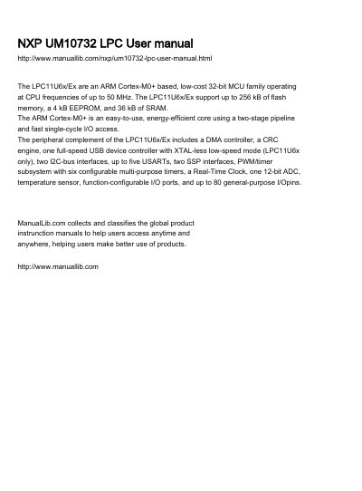
NXP UM10732 LPC User
The LPC11U6x/E6x family is a low-cost 32-bit microcontroller based on the ARM Cortex-M0+ core, operating at frequencies up to 50 MHz. These devices feature up to 256 kB of flash memory, 4 kB of EEPROM, and 36 kB of SRAM, designed for energy-efficient applications.
Read onlineNXP LPC11U6x specifications
| CPU Core | ARM Cortex-M0+ |
|---|---|
| Max CPU Frequency | 50 MHz |
| Flash Memory | Up to 256 kB |
| EEPROM | 4 kB |
| SRAM | 36 kB |
| ADC Resolution | 12-bit |
| ADC Sample Rate | 2 Msamples/s |
| Operating Voltage | 2.4 V to 3.6 V |
| Operating Temperature | -40 °C to +105 °C |
| GPIO Pins | Up to 80 |
Source: NXP UM10732 LPC User
All NXP LPC11U6x documents by type
Day-to-day operation, settings and troubleshooting. Start here if the product is already set up.
- NXP UM10732 LPC User 605 p
Ratings, dimensions and ordering codes, for selection and design work.
How to use the product for one specific task, with worked examples.
Questions answered in these manuals
What is the maximum CPU frequency of the LPC11U6x/E6x?
The microcontroller family operates at CPU frequencies of up to 50 MHz.
From: NXP UM10732 LPC User
What is the maximum sample rate of the ADC?
The 12-bit ADC supports sample rates of up to 2 Msamples/s.
From: NXP UM10732 LPC User
What is the maximum CPU frequency for the LPC11U6x microcontroller?
The microcontroller operates at CPU frequencies of up to 50 MHz.
What is the maximum amount of flash memory supported by the LPC11U6x?
The device supports up to 256 kB of flash memory.
Where are the IAP routines located?
The IAP routines are located in the Boot ROM at address Ox1FFF1FF0.
What precautions must be taken regarding interrupts during IAP?
Any access to flash memory must be avoided; if the vector table interrupt is in flash, all interrupts must be disabled prior to erase and write.