
The XC9210 is a synchronous PWM, PWM/PFM controller designed for low voltage step-down DC/DC converter applications. High efficiency is obtained through the use of a synchronous rectification topology. Efficiencies are maximized by using the low RDSon N-Channel MOSFET switch which replaces the catch diode used in standard buck circuits. The operation of the XC9210 series can be switched between PWM and PWM/PFM externally using the MODE pin. In PWM/PFM mode the XC9210 automatically switches from PWM to PFM during light loads and high efficiencies can be achieved over a wide range of load conditions. Output noise is reduced in PWM operation as the frequency is fixed. The XC9210 has an 0.9V (±2.0%) internal voltage, and using externally connected components, the output voltage can be set freely between 0.9V to 6.0V. With an internal switching frequency of 300kHz and 180kHz (custom) smaller, low cost external components can also be used. Soft-start time is internally set to 10msec offering protection against in-rush currents during start-up and preventing voltage overshoot.
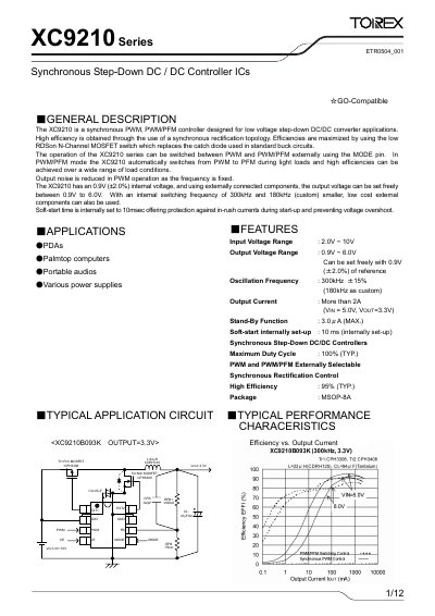
The XC9210 series are synchronous PWM/PWM‑PFM controller ICs designed for low‑voltage step‑down DC/DC converter applications. They feature a 0.9 V internal reference, selectable PWM or PWM‑PFM operation, and high efficiency up to 95 %.
The document provides pin assignments, electrical characteristics, recommended external components, layout guidelines, and marking information for the MSOP‑8A package, along with typical application circuits for PDAs, palmtop computers, and portable audio devices.
| Input Voltage Range | 2.0 V – 10 V |
|---|---|
| Output Voltage Range | 0.9 V – 6.0 V (adjustable) |
| Oscillation Frequency | 300 kHz (typ.) / 180 kHz (custom) |
| Maximum Output Current | >2 A (VIN=5 V, VOUT=3.3 V) |
| Efficiency (typ.) | 95 % (typ.) |
| Package | MSOP‑8A |
| Stand‑by Current | 3 µA (max) |
| Soft‑Start Time | 10 ms (typ.) |
| Maximum Duty Cycle | 100 % (typ.) |
The internal reference voltage (FB pin) is 0.9 V (±2.0 %).
The output voltage is set by external split resistors according to VOUT = 0.9 × (RFB11 + RFB12) / RFB12.
The standby current is limited to 3 µA when the CE pin disables the chip.
Yes, the mode can be selected externally via the MODE pin; PWM/PFM automatic switching is enabled when the PWM pin is low.