
XC9206/XC9207/XC9208 series is a group of DC/DC converters with a built-in 0.4Ω P-channel driver transistor, offered in a SOT-25 package. The ICs are designed to provide high efficiencies and a stable power supply with an output current of 500mA using only a coil, a diode and two ceramic capacitors connected externally. Minimum operating voltage of the XC9206/9207 is 1.8V and 2.0V for XC9208. Output voltage is internally programmable in a range from 0.9V to 4.0V in 100mV increments (accuracy: ±2.0%). Oscillation frequency is selectable from 300kHz, 600kHz and 1.2MHz so that the frequency best suited to your particular application can be selected. Each series features different operation modes: PWM control (XC9206 series), automatic PWM/PFM switching control (XC9207 series) and manual PWM/PFM switching control (XC9208 series). The series gives fast transient response, low ripple and high efficiency over the full range of load (from light load to high output current conditions). The soft start and current control functions are internally optimized. During stand-by, all circuits are shutdown to reduce current consumption to as low as 1.0μ A or less. With the built-in U.V.L.O. (Under Voltage Lock Out) function, the internal P-channel driver trans
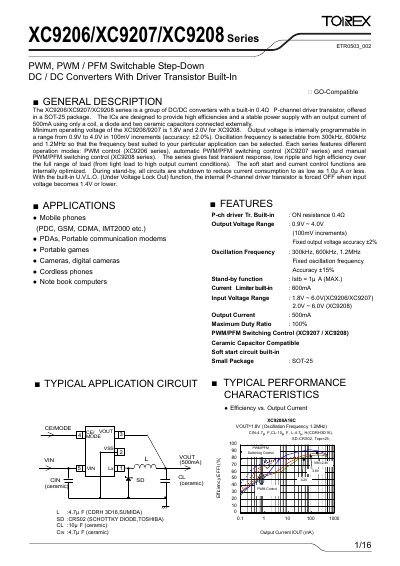
The XC9206/XC9207/XC9208 series are step‑down DC‑DC converters with a built‑in 0.4 µΩ P‑channel driver transistor, offered in a compact SOT‑25 package. They provide up to 500 mA output current using only an external coil, a diode and two ceramic capacitors. The series supports three operating modes: PWM control (XC9206), automatic PWM/PFM switching (XC9207) and manual PWM/PFM switching (XC9208).\nKey features include programmable output voltage from 0.9 V to 4.0 V in 100 mV steps, selectable oscillation frequencies of 300 kHz, 600 kHz or 1.2 MHz, a standby current as low as 1 µA, and built‑in UVLO that disables the driver when VIN ≤ 1.4 V.
| Output Voltage Range | 0.9 V ~ 4.0 V (100 mV increments) |
|---|---|
| Maximum Output Current | 500 mA |
| Input Voltage Range | 1.8 V ~ 6.0 V (XC9206/7) / 2.0 V ~ 6.0 V (XC9208) |
| Oscillation Frequency Options | 300 kHz, 600 kHz, 1.2 MHz |
| Stand‑by Current | ≤ 1 µA |
| Built‑in P‑channel Driver ON Resistance | 0.4 µΩ |
Driving the CE/MODE pin low puts the IC into shutdown, reducing current consumption to near zero.