
This document introduces the JTAG and In-System Programmability features of the Altera MAX II devices.
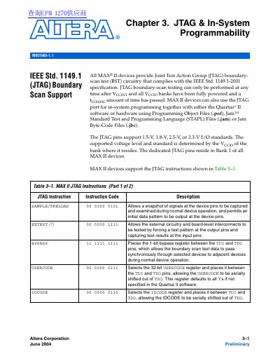
The document describes how MAX II devices comply with IEEE Std. 1149.1 for Joint Test Action Group (JTAG) boundary-scan testing. It lists specific JTAG instructions such as SAMPLE/ PRELOAD, EXTEST, BYPASS, USERCODE, IDCODE, HIGHZ, CLAMP, and user-defined chains (USER0/USER1), along with their binary codes and functions.
| JTAG Voltage Standards Supported | 1.5-V, 1.8-V, 2.5-V, or 3.3-V |
|---|---|
| JTAG Pin Location | Bank 1 |
| Instruction Register Length | 10 bits |
| USERCODE Register Length | 32 bits |
| EPM240 Boundary-Scan Register Length | 240 |
| EPM570 Boundary-Scan Register Length | 480 |
| EPM1270 Boundary-Scan Register Length | 636 |
| EPM2210 Boundary-Scan Register Length | 816 |
Supported instructions include SAMPLE/ PRELOAD, EXTEST, BYPASS, USERCODE, IDCODE, HIGHZ, CLAMP, and user-defined chains (USER0/USER1).
For TCK frequencies of 10 MHz, erasing takes less than one second for EPM240 devices.
The ISP_DONE bit prevents all I/O pins from driving until it is programmed to ensure safe operation if programming is interrupted.