
TB6539N/F is a 3-phase full-wave sine-wave PWM brushless motor control from Toshiba
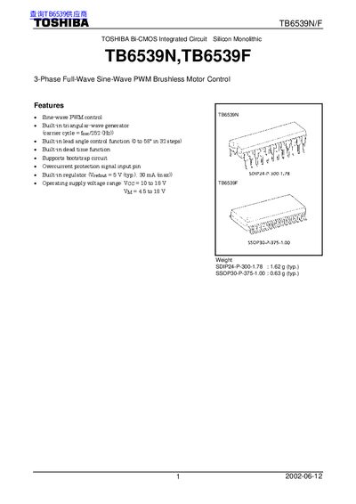
This document provides technical specifications and pin descriptions for the Toshiba TB6539N and TB6539F, which are silicon monolithic Bi-CMOS integrated circuits. These chips feature built-in triangular-wave generators, lead angle control functions, and overcurrent protection signals designed for 3-phase full-wave sine-wave PWM brushless motor control.
| Supply voltage (Vcc) | 10 to 18 V |
|---|---|
| Reference voltage output (Vrefout) | 5 V (typ.), 30 mA (max) |
| Operating temperature | -30 to 115 °C |
| Crystal oscillation frequency range | 2 to 8 MHz |
| Lead angle control range | 0 to 58° in 32 steps |
The maximum operating supply voltage Vcc is 18 V.
Yes, it includes a built-in regulator providing a reference voltage of 5 V typical.
The LA input pin sets the lead angle from 0 to 58 degrees in 32 steps.