
PM50CL1B060 is a three-phase 50A, 600V intelligent power module, which uses the fifth generation full-gate CSTBTTM chip, integrates drive and protection circuit, and has overcurrent, overvoltage, undervoltage, short circuit protection, and temperature protection functions.
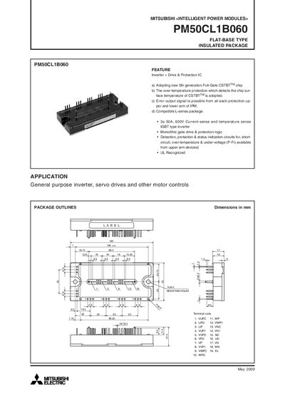
The PM50CL1B060 is a flat‑base, insulated Intelligent Power Module that integrates an inverter, drive, and protection IC. It features a 5th‑generation Full‑Gate CSTBT™ chip, over‑temperature protection, and fault output signals for both upper and lower arms. The module is compatible with L‑series packages and is UL recognized for general‑purpose inverter, servo drive, and motor control applications.
The document details electrical characteristics, maximum ratings, mechanical dimensions, thermal resistance, and recommended PCB layout practices. It also includes performance curves, switching loss data, and transient thermal impedance graphs to aid designers in implementing the module safely and efficiently.
| Collector‑Emitter Voltage (VCES) | 600 V |
|---|---|
| Continuous Collector Current (Ic) | 50 A |
| Peak Collector Current | 100 A |
| Power Dissipation (Pc) | 284 W |
| Junction Temperature Range | -20 °C to +150 °C |
| Supply Voltage (VD) Range | 13.5 V – 16.5 V |
| Weight | 340 g |
The module can handle a continuous collector current of 50 A.
The recommended supply voltage (VD) is between 13.5 V and 16.5 V.
Minimize wiring length between the opto‑coupler and the IPM input terminals and keep stray capacitance low.
The module includes over‑temperature protection, short‑circuit protection, under‑voltage protection, and fault‑output signals for each arm.