
This document describes the features and characteristics of the MITSUBISHI Intelligent Power Module PM25RLB120 in May 2005. The module adopts a new 5th generation IGBT (CSTBT) chip, which improves performance. It has temperature protection with error output from all upper and lower arms of the IPM. The current rating of the brake part has increased by 60%. The module also features detection, protection, and status indication circuits for short-circuit, over-temperature, and under-voltage. It is suitable for general-purpose inverters, servo drives, and other motor control applications.
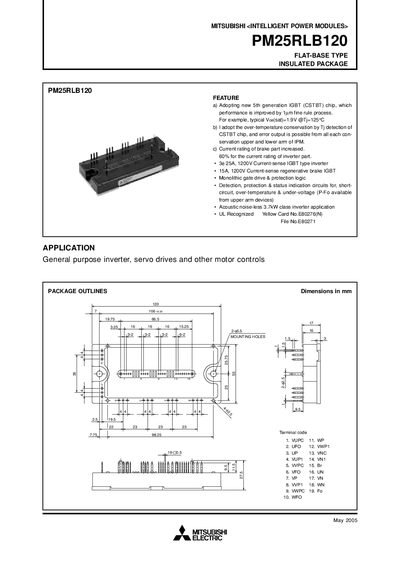
This manual describes the Mitsubishi PM25RLB120 Intelligent Power Module, a flat‑base insulated IGBT‑based power module for general‑purpose inverter, servo drive and motor control applications. It includes feature highlights, internal block diagrams, maximum ratings, thermal and mechanical data, and recommended operating conditions.
The document also gives detailed testing precautions, wiring recommendations, performance curves, and diode characteristics to help designers and technicians integrate the module safely and reliably into their systems.
| Continuous Collector Current (Inverter Part) | 25 A |
|---|---|
| Peak Collector Current (Inverter Part) | 50 A |
| Power Dissipation (Inverter Part) | 150 W |
| Junction Temperature Range | -20 °C to +150 °C |
| Weight | 340 g |
| Protected Supply Voltage | 13.5 V – 16.5 V |
The inverter part can handle a continuous collector current of 25 A.
The peak collector current rating for the inverter part is 50 A.
The module is rated for junction temperatures from –20 °C up to +150 °C.