
This document describes the PS21564-P dual-in-line package intelligent power module from MITSUBISHI Semiconductor in September 2005. It features insulated terminal and transfer-mold type. The product is designed for AC100V~200V inverter drive for small power motor control, providing 600V/15A low-loss 5th generation inverter bridge for three phase DC-to-AC power conversion.
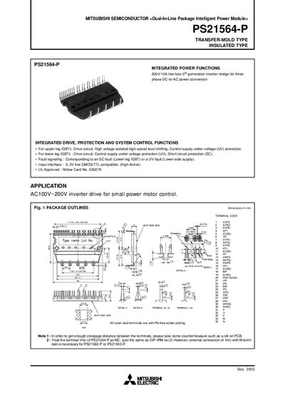
The PS21564-P is a dual‑in‑line package (DIP) intelligent power module that integrates drive, protection, and system‑control functions for three‑phase DC‑to‑AC inverter bridges. It supports 600 V/15 A low‑loss operation and includes upper‑leg and lower‑leg IGBT drive circuits, fault signaling, and input interfaces compatible with 3.5 V CMOS/TTL logic.
The document lists maximum electrical ratings, thermal characteristics, mechanical dimensions, recommended mounting torque, and wiring guidelines. It also describes the timing of protective functions such as short‑circuit and under‑voltage protection, and provides example application circuits and CPU I/O interface recommendations.
| Supply voltage (Veco) | 450 V |
|---|---|
| Collector‑emitter voltage (VCES) | 600 V |
| IGBT collector current (continuous) | 15 A |
| Weight | 20.9 g |
The maximum supply voltage (Veco) is 450 V applied between the P and N terminals.
Fo is an open‑drain output and should be pulled up to the 5 V power supply with a resistor of about 10 kΩ.