
This application note provides RF characteristics data of MGF0906B.
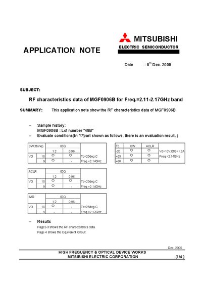
The document presents measured RF characteristics of the MGF0906B semiconductor device for frequencies between 2.11 GHz and 2.17 GHz. Test conditions such as supply voltage, bias current and temperature are listed, and the results include power‑output versus input power, ACLR, IMD and other key parameters.
Pages 2‑3 contain the detailed RF test curves, while page 4 shows the equivalent circuit and the test‑fixture component values used during measurement. The note is intended for engineers evaluating the device in wireless‑communication applications.
| Frequency band | 2.11‑2.17 GHz |
|---|---|
| Test current (IDQ) | 1.2 A |
| Test temperature (Tc) | 25 °C |
| Capacitor C1/C2 | 20 pF |
| Capacitor C3/C4 | 100 pF |
| Capacitor C5 | 4.7 µF |
| Capacitor C6 | 1000 pF |
| Capacitor C8 | 2.8 pF |
| Inductor L1/L2 | 71 nH |
| Resistor R1 | 51 Ω |
| Resistor R2 | 100 Ω |
| Board material | FR4, thickness 0.8 mm |
| Dielectric constant | 4.4 |
The RF test data cover the 2.11 GHz to 2.17 GHz band.
The measurements were performed with a supply voltage of 10 V and a bias current of 1.2 A.
The fixture uses C1/C2 = 20 pF, C3/C4 = 100 pF, C5 = 4.7 µF, C6 = 1000 pF, C8 = 2.8 pF, C9 = 2 pF, L1/L2 = 71 nH, R1 = 51 Ω and R2 = 100 Ω.
The board is made of FR4 with a thickness of 0.8 mm and a dielectric constant of 4.4.