
This document describes the features and characteristics of UMF6N Transistors Rev.B 1/5 Power Management circuit, which includes dual transistors 2SA2018 and 2SK3019 housed independently in a UMT package.
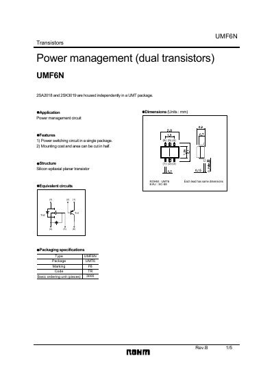
The UMF6N component integrates two independent transistors, 2SA2018 and 2SK3019, in a compact UMT6 package, offering a power‑switching solution that reduces mounting cost and board area. The datasheet outlines its structure, equivalent circuits, and key features for power‑management applications.
Detailed electrical parameters are listed, including absolute maximum ratings, typical and maximum values for breakdown voltages, current limits, transition frequency, and capacitances. Application notes and safety notices guide designers on proper usage, derating, and compliance considerations.
| Package type | UMT6 |
|---|---|
| Collector‑emitter breakdown voltage (VCEO) | -12 V |
| Maximum collector current (IC) | -200 mA |
| Transition frequency (fT) | 260 MHz |
| Maximum power dissipation per element | 120 mW |
The UMF6N package contains the 2SA2018 and 2SK3019 transistors.
The maximum collector‑emitter voltage (VCEO) is -12 V.
The typical transition frequency (fT) is 260 MHz.
Each element should not exceed 120 mW of power dissipation.