
The IR2130/IR2132(J)(S) is a high voltage, high speed power MOSFET and IGBT driver with three independent high and low side referenced output channels. Proprietary HVIC technology enables ruggedized monolithic construction. Logic inputs are compatible with CMOS or LSTTL outputs, down to 2.5V logic. A ground-referenced operational amplifier provides analog feedback of bridge current via an external current sense resistor. A current trip function which terminates all six outputs is also derived from this resistor. An open drain FAULT signal indicates if an over-current or undervoltage shutdown has occurred. The output drivers feature a high pulse current buffer stage designed for minimum driver cross-conduction. Propagation delays are matched to simplify use at high frequencies. The floating channel is designed for bootstrap operation, fully operational to +600V, and tolerant to negative transient voltage dV/dt immune. The gate drive supply range is from 10 to 20V. Undervoltage lockout is available for all channels. Over-current shutdown turns off all six drivers. The drivers are independent half-bridge drivers. The outputs are out of phase with inputs. Cross-conduction prevention logic is included. The product is also available in LEAD-FREE.
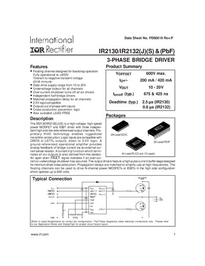
The IR2130/IR2132 series is a high‑voltage, high‑speed power MOSFET and IGBT driver with three independent high‑ and low‑side referenced output channels. It offers floating channels for bootstrap operation, over‑current shutdown, and undervoltage lockout, and is compatible with 2.5 V logic inputs. The device includes an operational‑amplifier feedback circuit for current sensing and a fault output indicating over‑current or undervoltage conditions.
The driver is offered in multiple packages—28‑lead PDIP, 28‑lead SOIC (wide body), and 44‑lead PLCC without 12 leads—providing flexibility for different board layouts. Typical applications include high‑frequency switching power supplies and motor drives that require up to 600 V floating supply voltage.
| Gate drive supply range | 10 V to 20 V |
|---|---|
| Floating supply voltage (max) | 600 V |
| Output high short‑circuit pulsed current (IO+) | 200 mA (typ) – 250 mA (max) |
| Output low short‑circuit pulsed current (IO‑) | 420 mA (typ) – 500 mA (max) |
| Turn‑on propagation delay (IR2130) | 675 ns (typ) |
| Turn‑on propagation delay (IR2132) | 425 ns (typ) |
| Deadtime (IR2130) | 2.5 µs (typ) |
| Deadtime (IR2132) | 0.8 µs (typ) |
| Power dissipation (28‑Lead DIP) | 1.5 W |
The driver can operate with a floating supply voltage up to 600 V.
The device is available in 28‑lead PDIP, 28‑lead SOIC (wide body), and 44‑lead PLCC without 12 leads.
Logic inputs are compatible with CMOS or LSTTL outputs down to 2.5 V logic.
The driver requires a gate‑drive supply voltage between 10 V and 20 V.