
This document describes the typical features of a half-bridge driver, including floating channel for bootstrap operation, operational up to +600V, tolerant to negative transient voltage, undervoltage lockout, compatible with 3.3V, 5V and 15V input logic, cross-conduction prevention logic, matched propagation delay, high side output in phase with input, internal dead-time, lower di/dt gate driver, shutdown input, and availability in lead-free packages.
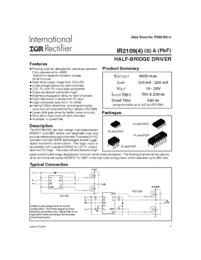
The IR2109(4) series provides a floating half‑bridge driver designed for bootstrap operation up to 600 V. It supports 3.3 V, 5 V and 15 V logic inputs, includes undervoltage lockout on both channels, and features internal 540 ns dead‑time that can be programmed up to 5 µs with an external resistor.
The document lists electrical specifications, pin assignments, timing diagrams, and package outlines for the lead‑free and leaded versions (PDIP, SOIC). Ordering information and qualification notes for industrial use are also included.
| Maximum supply voltage (VOFFSET) | 600 V |
|---|---|
| Gate‑drive supply range (VOUT) | 10 V – 20 V |
| Internal dead‑time | 540 ns (programmable up to 5 µs) |
| Power dissipation (PD) – 8‑Lead PDIP | 1.0 W |
| Thermal resistance (RthJA) – 8‑Lead PDIP | 125 °C/W |
| Junction temperature (TJ) | 150 °C |
| Logic "1" input voltage (VIH) for high side | 2.9 V |
| Logic "0" input voltage (VIL) for low side | 0.8 V |
The device is rated for a maximum supply voltage of 600 V.
Yes, the internal dead‑time of 540 ns can be programmed up to 5 µs using an external resistor on the DT pin.
The driver accepts 3.3 V, 5 V and 15 V input logic levels.
The device is specified for an ambient temperature range of –40 °C to +125 °C.