
The BTS 4141N is a high-side power switch product from Infineon, which has short-circuit protection, current limiting, overload protection, overvoltage protection, undervoltage shutdown, switching inductive loads, output negative voltage clamping, CMOS compatible input, thermal shutdown, ESD protection, loss of GND and loss of Vbb protection, very low standby current, reverse battery protection with external resistor and improved electromagnetic compatibility (EMC).
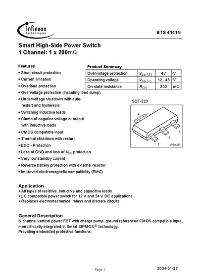
The BTS 4141N smart high‑side power switch integrates a vertical N‑channel power FET with a charge pump and CMOS‑compatible input. It provides multiple protection features such as short‑circuit, over‑voltage, overload, thermal shutdown, and reverse‑battery protection, making it suitable for replacing electromechanical relays in 12 V‑24 V DC applications.
The datasheet includes electrical characteristics, maximum ratings, EMC data, and package information, allowing designers to evaluate the device for resistive, inductive, or capacitive loads and to implement it in automotive, industrial, or consumer electronics designs.
| Operating voltage (Vbb on) | 12 – 45 V |
|---|---|
| Continuous input voltage (Vin) | -10 … 48 V |
| Standby current (off) | ≤ 40 µA |
| Thermal shutdown temperature (Tt) | 135 °C |
The device operates with a supply voltage (Vbb) from 12 V to 45 V.
The on‑state resistance (Ron) is specified as 200 mΩ at 25 °C.
The nominal load current is limited to 0.7 A, with higher limits defined by the current‑limitation circuit.