
PM450CLA120 is a three-phase 450A, 1200V intelligent power module that uses the fifth-generation IGBT chip with a 1µm fine line process to improve performance.
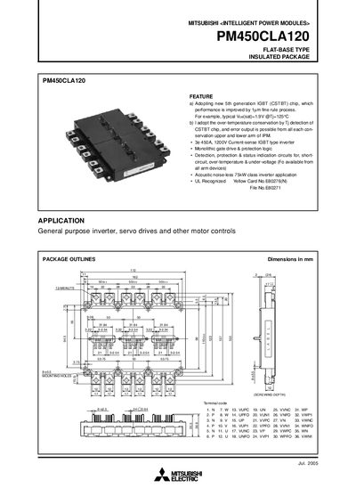
The Mitsubishi Electric PM450CLA120 is a flat‑base, insulated intelligent power module featuring a 5th‑generation IGBT (CSTBT) chip, 450 A continuous and 900 A peak current capability, and built‑in protection functions such as over‑temperature, short‑circuit, and under‑voltage detection. The manual provides detailed electrical ratings, mechanical dimensions, and recommended operating conditions for general‑purpose inverter and servo drive applications.
Key sections cover internal block diagrams, maximum ratings, mechanical mounting data, testing precautions, and performance curves. Practical design notes advise PCB layout, capacitor placement, and noise mitigation to ensure stable and safe operation of the module.
| Continuous Collector Current (Ic) | 450 A |
|---|---|
| Junction Temperature Range | -20 °C ~ +150 °C |
| Control Supply Voltage (VD) | 13.5 V ~ 16.5 V |
| Weight | 1250 g |
The module is rated for a continuous collector current of 450 A at 25 °C.
It includes over‑temperature detection, short‑circuit protection, under‑voltage protection, and fault output signals for each arm of the IPM.
The control supply voltage (VD) should be between 13.5 V and 16.5 V, with Vb and VCIN both at 15 V.
Minimize wiring length between the opto‑coupler and IPM inputs, keep stray capacitance low, and place low‑impedance decoupling capacitors between VCC and GND of each fast‑switching opto‑coupler.