
This document describes the features and characteristics of the MITSUBISHI Semiconductor PS21267-P/AP intelligent power module used in three-phase DC-to-AC power conversion applications.
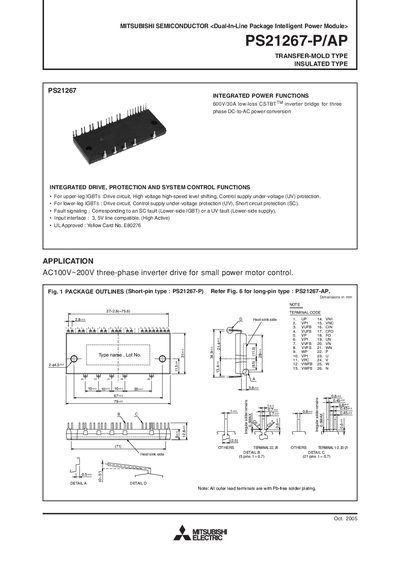
The PS21267-P/AP is a dual‑in‑line package intelligent power module (IPM) designed for three‑phase inverter drives up to 600 V and 30 A. It integrates drive, protection, and system‑control functions for both upper‑leg and lower‑leg IGBTs, including under‑voltage and short‑circuit protection.
The manual details electrical ratings, thermal characteristics, mechanical dimensions, recommended mounting torque, and wiring practices. It also includes timing charts for protection functions and example application circuits to help designers implement the module safely and efficiently.
| Supply voltage (Veco) | 450 V |
|---|---|
| Collector‑emitter voltage (VCES) | 600 V |
| Continuous collector current (Ic) | 30 A |
| Power dissipation per chip | 55.5 W |
| Maximum junction temperature (average) | 125 °C |
| Weight | 54 g |
| Mounting torque (M4 screw) | 1.18 N·m (recommended) |
| Control supply voltage (VD) | 13.5 V – 16.5 V |
Each IGBT can handle a continuous collector current of 30 A at 25 °C.
Place the shunt resistor as close as possible to the P and N1 terminals, keeping wiring inductance below 10 nH.
The control supply voltage (VD) should be between 13.5 V and 16.5 V.
The module includes upper‑leg and lower‑leg IGBT drive circuits, under‑voltage protection, short‑circuit protection, and fault signaling.