
The document describes the features and characteristics of the PS21964-4 integrated power function, including a 600V/15A low-loss 5th generation IGBT inverter bridge for three-phase DC-to-AC power conversion. It is designed for AC100V~200V three-phase inverter drive for small power motor control.
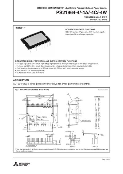
The PS21964‑4/4A/4C/4W is a dual‑in‑line package (DIP) intelligent power module that integrates drive, protection, and system‑control functions for three‑phase inverter drives up to 600 V/15 A. It includes upper‑leg and lower‑leg IGBT drive circuits, under‑voltage and short‑circuit protection, and a fault‑signaling output.
The document details mechanical dimensions, electrical ratings (e.g., 600 V VCES, 15 A continuous collector current), recommended operating conditions, wiring recommendations, and timing charts for protection functions. It also provides example application circuits and guidelines for mounting and thermal management.
| Supply voltage (Veco) | 450 V |
|---|---|
| Collector‑emitter voltage (VCES) | 600 V |
| Continuous collector current | 15 A |
| Isolation voltage (pins to heat‑sink) | 1500 V |
The maximum supply voltage (Veco) is 450 V applied between the P‑N terminals.
A mounting torque of 0.69 Nm (typical) is recommended, with a range of 0.59 Nm to 0.78 Nm.
The isolation voltage between pins and the heat‑sink plate should be at least 1500 V.