
This document introduces the MGF0905A high-power GaAs FET, which is designed for UHF band amplifiers and features high output power, high power gain, and high power added efficiency.
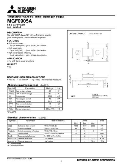
The MGFO0905A is a high‑power GaAs field‑effect transistor (FET) designed for use in UHF band power amplifiers. It features an N‑channel Schottky gate and is specified for L & S band operation at up to 2.5 W (non‑matched). The document provides the device’s electrical characteristics, recommended bias conditions, and safety guidelines.
Key specifications include a typical output power of 34 dBm at 1.65 GHz with 26 dBm input, a typical gain of 8 dB, and a power‑added efficiency of 40 %. Absolute maximum ratings list a gate‑to‑drain voltage of –17 V, gate‑to‑source voltage of –17 V, drain current up to 3.2 A, and total power dissipation of 12 W. Safety notes advise proper circuit design practices and liability disclosures.
| Typical Output Power (Po) | 34.0 dBm @ 1.65 GHz, Pin=26 dBm |
|---|---|
| Power Added Efficiency (PAE) | 40 % (typical) @ 1.65 GHz, Pin=26 dBm |
| Gain (Gp) | 8.0 dB (typical) @ 1.65 GHz, Pin=26 dBm |
| Drain Current (ID) | 3 200 mA (max) |
| Gate‑to‑Drain Voltage (Vgd) | -17 V (max) |
| Gate‑to‑Source Voltage (Vgs) | -17 V (max) |
| Total Power Dissipation (PT) | 12 W (max) |
| Storage Temperature Range | -65 °C to +175 °C |
| Thermal Resistance (case) | 12.5 °C/W |
| Typical Saturated Drain Current (IDS) | 2 400 mA @ VDS=3 V, VGS=0 V |
The typical output power is 34 dBm at 1.65 GHz with a 26 dBm input.
Recommended bias is Vds = 8 V, Ids = 800 mA, and Rg = 100 Ω.
The maximum gate‑to‑drain voltage is –17 V.