
This document introduces the features and characteristics of Mitsubishi Electric's third generation intelligent power modules.
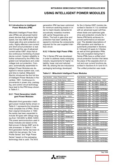
This manual describes Mitsubishi Intelligent Power Modules (IPMs), including third‑generation and V‑Series high‑power families. It explains the hybrid design that combines IGBTs with integrated gate‑drive and protection circuitry, and outlines the benefits of reduced size, cost and improved reliability.
The document details the two construction types (multilayer epoxy for low‑power devices and ceramic isolation for high‑power devices), provides maximum ratings, thermal and electrical characteristics, recommended operating conditions, and test circuits for evaluating performance and safety.
| Maximum DC bus voltage (VCC) | Maximum DC bus voltage applied between P‑N |
|---|---|
| Maximum collector‑emitter voltage (VCES) | Maximum off‑state collector‑emitter voltage at applied control input off signal |
| Junction temperature range | Tj ≤ 150°C |
| Thermal resistance (junction‑to‑case) | Maximum value of thermal resistance between junction and case per switch |