
This document describes the features of using Mitsubishi IGBT modules, including their ruggedness, low loss, and ease of use. Advanced processing technologies are utilized to achieve low on-state saturation voltages while maintaining high switching speed for 20kHz operation. The document also explains the structure and operation of IGBT modules and provides a comparison with MOSFET and BJT devices.
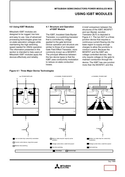
This manual provides detailed information on Mitsubishi IGBT (Insulated Gate Bipolar Transistor) modules, covering their structure, silicon design, wafer processing, and packaging. It explains how the devices operate, compares them with MOSFETs and BJTs, and describes the advantages of Mitsubishi’s U‑Series package.
The document also lists absolute maximum ratings, electrical characteristics, test circuits, safe‑operation area considerations, and performance curves. Engineers can use the data to design reliable power conversion circuits and to evaluate short‑circuit and switching behavior of the modules.
The U‑Series package reduces internal inductance to about one third of conventional modules and eliminates the strain‑relieving “S” bends, simplifying assembly and improving reliability.
VCES is defined as the maximum off‑state collector‑emitter voltage with the gate‑emitter shorted.
Turn‑on delay time is the time from VGE = 0 V to IC reaching 10 % of its final value.