
Key facts
- Brand
- Catalyst
- Model
- CAT1025
- Industry
- Industrial
- Documents
- 2
- Languages
- EN
- Last added
- 2012-06-05
Start here
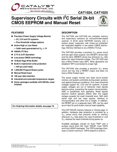
Catalyst CAT1024 CAT1025 User Manual
This manual describes the CAT1024 and CAT1025 supervisory circuits that combine a 2‑kbit serial EEPROM with a power‑monitoring and reset controller. It covers features such as precision voltage monitoring, multiple reset‑threshold options, manual reset input, and write‑protect functionality for the CAT1025.
The document includes pin‑out diagrams, absolute maximum ratings, electrical characteristics, AC timing parameters, reliability data, and detailed ordering information for the various package options (PDIP, SOIC, TSSOP, TDFN, MSOP).
Catalyst CAT1025 specifications
| Memory Size | 2k-bit CMOS EEPROM |
|---|---|
| Bus Speed | 400kHz |
| Operating Voltage Range | 3.0V to 5.5V |
| Program/Erase Cycles | 1,000,000 |
| Data Retention | 100 years |
| Package Types | 8-pin DIP, SOIC, TSSOP, MSOP & TDFN (3x3mm) |
All Catalyst CAT1025 documents by type
Day-to-day operation, settings and troubleshooting. Start here if the product is already set up.
Ratings, dimensions and ordering codes, for selection and design work.
Questions answered in these manuals
How does the manual reset function work?
Pulling the MR input low generates a Reset condition that remains active for the timeout period after returning to high.
What is the maximum clock frequency for the I2C bus?
The device supports a PC bus speed of up to 400kHz.
What is the reset timeout period after power‑up?
The reset output remains active for about 200 ms after power‑up before it is released.
How many program/erase cycles does the device support?
The device supports up to 1,000,000 program/erase cycles per byte.