
The Ningbo Anson Hi Series servo drive manual provides safety guidelines, installation steps, wiring diagrams, parameter settings, and troubleshooting for…
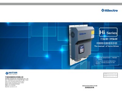
This manual covers the complete lifecycle of the Hi Series servo drives, starting with safety usage standards and product arrival checks, followed by detailed installation instructions and recommended brake‑resistor selection. It also includes wiring diagrams for various series (Hi200/202, Hi260/262, Hi282) and guidance on connecting peripheral equipment.
Further sections describe the digital and Wi‑Fi operators, a comprehensive parameter list, alarm inspection procedures, and commissioning steps. Special cases such as in‑built motor models, fault handling, and parameter modification are explained with step‑by‑step instructions. This manual is written in Chinese.
| Rated output current | 75 A ~ 300 A |
|---|---|
| Voltage range | 3‑phase 380 V ~ 440 V |
| Overload capacity | 150 % for 60 s (5 Hz +) |
| Maximum applicable motor power per shell | 37 kW ~ 160 kW depending on shell code |
Ensure the power voltage matches the drive’s rated voltage, verify that input and output wiring positions are correct, confirm that no short circuits exist, and that the drive cover is securely closed.
No, the drives must not be used in areas requiring explosion protection; a special explosion‑proof cabinet should be used instead.
Select a brake resistor based on the drive’s power rating as shown in Table 1.4; liquid‑cooled drives have built‑in resistors, while wind‑cooled drives require external selection.
The torque range for R‑shell (37–90 kW) main loop terminals is 6 ~ 8 Nm.