
The IXYS IXGH40N60 and IXGM40N60 IGBTs are 600 V, 75 A high‑speed devices with low VCE(sat) and detailed electrical specifications.
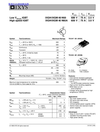
The IXGH/IXGM 40N60 series are high‑speed IGBTs rated for 600 V collector‑emitter voltage and 75 A continuous current. They are offered in TO‑247 and TO‑204 packages with low saturation voltages (typical 2.5 V for 40N60 and 3.0 V for 40N60A) and feature MOSFET‑type gate turn‑on for simple drive.
These devices are intended for AC motor speed control, DC servo and robot drives, UPS, switch‑mode and resonant‑mode power supplies, and other high‑power applications. The datasheet provides maximum ratings, test conditions, characteristic curves, switching times, and thermal impedance data.
| Collector‑Emitter Voltage (VCE) | 600 V |
|---|---|
| Continuous Collector Current (IC) | 75 A |
| Weight (TO‑247) | 6 g |
| Maximum Lead Temperature for Soldering | 300 °C |
| Turn‑on Delay (td(on)) | 100 ns |
| Turn‑off Delay (td(off)) | 600 ns |
| Thermal Resistance Junction‑to‑Case (RthJC) | 0.5 K/W |
| Thermal Resistance Case‑to‑Ambient (RthCK) | 0.25 K/W |
The devices are rated for a maximum VCE of 600 V.
The junction‑to‑case thermal resistance is 0.5 K/W.