
The SY89421V is a digital Phase Locked Loop based on Micrel-Synergy's differential PLL technology. It is capable of operating in the 30MHz to 560MHz reference input frequency range, and up to 2000MHz with the HFIN input and an external VCO. Use of a phase-frequency detector results in excellent PLL locking and tracking characteristics. Error correction voltages are generated by the detector if either phase or frequency deviations occur. The VCO has a frequency range covering more than a 2:1 ratio from 480MHz to 1120MHz. Feedback for the loop is realized by connecting FOUT, FOUT to FIN, FIN by means of external circuitry. This allows the flexibility of inserting additional circuitry off-chip in the feedback paths, such as an additional divider and/or buffer. Pulldown resistors are required for the FOUT and FOUT pins. High frequency inputs HFIN, HFIN and corresponding outputs HFOUT, HFOUT are featured for use with external components such as an active loop filter and a high frequency VCO. Select pins S1 and S2 are used to program the N divider for optimum VCO operation, in other words with the VCO in the center of its range. Select pin S3 allows bypassing the N divider enabling the PLL to output the VCO directly. Select pin S4 is used to select off-chip or on-chip VCO. Select pin S5 enables the divide-by-two prescaler, which is useful in frequency doubling applications. All Select pins are TTL compatible.
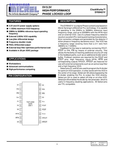
The SY89421V is a digital Phase‑Locked Loop based on Micrel‑Synergy's differential PLL technology. It supports 3.3 V or 5 V supply options and operates with a reference input range of 30 MHz to 560 MHz, extending up to 2 GHz with an external VCO. Features include low‑jitter differential design, frequency doubler mode, and PECL differential outputs.
The document details pin assignments, loop‑filter component values, frequency‑selection tables, absolute‑maximum ratings, and electrical characteristics for both 3.3 V and 5 V versions. Ordering codes (SY89421VZC, SY89421VZCTR) and mechanical dimensions are also provided.
| Reference Input Frequency Range | 30 MHz – 560 MHz |
|---|---|
| Power Supply Voltage (5 V version) | 4.75 V – 5.25 V |
| Power Supply Voltage (3.3 V version) | 3.135 V – 3.465 V |
| High Frequency Input Capability | Up to 2000 MHz |
The device accepts reference inputs from 30 MHz to 560 MHz.
It can be powered from either 3.3 V or 5 V supplies.
The high‑frequency input (HFIN) can accept signals up to 2 GHz.