
The MAX9424–MAX9427 high-speed, low-skew quad PECL-to-ECL translators are designed for high-speed data and clock driver applications. These devices feature an ultra-low 0.24ps(RMS) random jitter and channel-to- channel skew is less than 90ps in asynchronous mode. The four channels can be operated synchronously with an external clock, or in asynchronous mode determined by the state of the SEL input. An enable input provides the ability to force all the outputs to a differential low state. The parts differ from one another by their input and out- put termination options. The input options are an open input or an internal differential 100Ω termination. The output options are an open-emitter output or a series 50Ω termination. See Ordering Information. The MAX9424–MAX9427 operate from a positive voltage supply of +2.375V to +5.5V, and a negative supply volt- age of -2.375V to -5.5V and operate across the extended temperature range of -40°C to +85°C. They are offered in 32-pin 5mm x 5mm TQFP and space-saving 5mm x 5mm QFN packages. Applications include Data and Clock Driver and Buffer, Central Office Backplane Clock Distribution, DSLAM Backplane, Base Station, and ATE. Features include 0.24ps RMS Added Random Jitter, 10ps Channel-to-Channel Skew in Synchronous Mode, Guaranteed 500mV Differential Output at 3GHz Clock Frequency, 420ps Propagation Delay in Asynchronous Mode, and Functionally Compatible with SK4426 (MAX9424), SK4430 (MAX9425), SK4436 (MAX9426), and SK4440 (MAX9427).
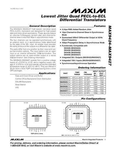
The MAX9424‑MAX9427 family are high‑speed, low‑skew quad PECL‑to‑ECL translators designed for data and clock driver applications. They feature an ultra‑low 0.24 ps RMS random jitter and less than 90 ps channel‑to‑channel skew in asynchronous mode, with optional synchronous operation via an external clock.
The devices are offered in 32‑pin 5 mm × 5 mm TQFP and 5 mm × 5 mm QFN packages. The datasheet details pin configurations, absolute maximum ratings, DC and AC electrical characteristics, typical operating curves, and package dimensions.
| Random Jitter | 0.24 ps RMS |
|---|---|
| Channel‑to‑Channel Skew (Synchronous) | 10 ps |
| Differential Output (3 GHz) | ≥ 500 mV |
| Propagation Delay (Asynchronous) | 420 ps |
| Supply Voltage Range (Positive) | +2.375 V to +5.5 V |
| Supply Voltage Range (Negative) | -2.375 V to -5.5 V |
| Package Options | 32‑pin 5 mm × 5 mm TQFP, 5 mm × 5 mm QFN |
The devices have an added random jitter of 0.24 ps RMS.
They operate from a positive supply of +2.375 V to +5.5 V and a negative supply of -2.375 V to -5.5 V.
The devices are available in 32‑pin 5 mm × 5 mm TQFP and 5 mm × 5 mm QFN packages.
The channel‑to‑channel skew is 10 ps in synchronous mode.