
The MAX1207 is a 3.3V, 12-bit analog-to-digital converter (ADC) featuring a fully differential wideband track-and-hold (T/H) input, driving the internal quantizer. The MAX1207 is optimized for low power, small size, and high dynamic performance. This ADC operates from a single 3.0V to 3.6V supply, consuming only 316mW, while delivering a typical signal-to-noise ratio (SNR) performance of 68.5dB at a 32.5MHz input frequency. The T/H-driven input stage accepts single-ended or differential inputs. In addition to low operating power, the MAX1207 features a 0.15mW power-down mode to conserve power during idle periods. A flexible reference structure allows the MAX1207 to use its internal precision bandgap reference or accept an externally applied reference. A common-mode reference is provided to simplify design and reduce external component count in differential analog input circuits. The MAX1207 supports both a single-ended and differential input clock drive. Wide variations in the clock duty cycle are compensated with the ADC’s internal duty-cycle equalizer. The MAX1207 features parallel, CMOS-compatible outputs. The digital output format is pin selectable to be either two’s complement or Gray code. A data-valid indicator eliminates external components that are normally required for reliable digital interfacing. A separate power input for the digital outputs accepts a voltage from 1.7V to 3.6V for flexible interfacing with various logic levels.
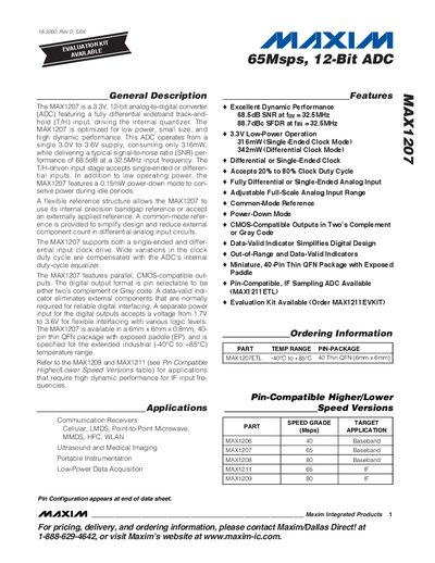
The MAX1207 is a 3.3 V, 12‑bit analog‑to‑digital converter (ADC) optimized for low power, small size, and high dynamic performance. It operates from a single 3.0 V to 3.6 V supply and offers both single‑ended and differential input configurations with a fully differential track‑and‑hold front end.
Key features include a typical SNR of 68.5 dB at a 32.5 MHz input frequency, a maximum sampling rate of 65 Msps, power‑down mode consuming only 0.15 mW, and a 40‑pin thin QFN (6 mm × 6 mm × 0.8 mm) package with an exposed paddle. The device supports CMOS‑compatible digital outputs selectable as two's complement or Gray code.
| Supply Voltage | 3.0 V to 3.6 V |
|---|---|
| Power Consumption (single‑ended clock) | 316 mW |
| Signal‑to‑Noise Ratio | 68.5 dB at 32.5 MHz |
| Maximum Sampling Rate | 65 Msps |
| Resolution | 12 bits |
| Operating Temperature Range | -40 °C to +85 °C |
| Package | 40‑pin thin QFN 6 mm × 6 mm × 0.8 mm with exposed paddle |
The device operates from a single supply of 3.0 V to 3.6 V.
It achieves a typical SNR of 68.5 dB at a 32.5 MHz input frequency.
It is available in a 40‑pin thin QFN package measuring 6 mm × 6 mm × 0.8 mm with an exposed paddle.
The ADC can sample up to 65 Msps.