
The MAX1434 is an octal, 10-bit analog-to-digital converter (ADC) with fully differential inputs, a pipelined architecture, and digital error correction incorporating a fully differential signal path. This ADC is optimized for low-power and high-dynamic performance in medical imaging instrumentation and digital communications applications. The MAX1434 operates from a 1.8V single supply and consumes only 767mW (96mW per channel) while delivering a 61dB (typ) signal-to-noise ratio (SNR) at a 5.3MHz input frequency. In addition to low operating power, the MAX1434 features a power-down mode for idle periods. An internal 1.24V precision bandgap reference sets the full-scale range of the ADC. A flexible reference structure allows the use of an external reference for applications requiring increased accuracy or a different input voltage range. The reference architecture is optimized for low noise. A single-ended clock controls the data-conversion process. An internal duty-cycle equalizer compensates for wide variations in clock duty cycle. An on-chip PLL generates the high-speed serial low-voltage differential signal (LVDS) clock. The MAX1434 has self-aligned serial LVDS outputs for data, clock, and frame-alignment signals. The output data is presented in two’s complement or binary format. The MAX1434 offers a maximum sample rate of 50Msps. See the Pin-Compatible Versions table below for 12-bit versions. This device is available in a small, 14mm x 14mm x 1mm package.
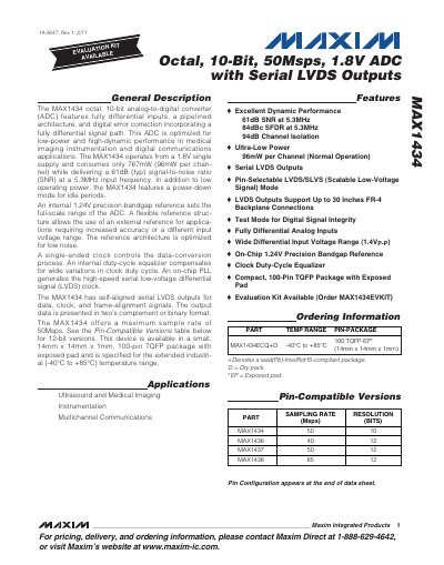
The MAX1434 is an octal, 10‑bit analog‑to‑digital converter designed for low‑power, high‑dynamic‑performance applications such as medical imaging and multichannel communications. It operates from a single 1.8 V supply, consumes only 96 mW per channel, and provides fully differential inputs with a 1.4 V p‑p range.
The device features serial LVDS outputs, selectable LVDS/SLVS mode, and a compact 100‑pin TQFP package (14 mm × 14 mm × 1 mm) rated for –40 °C to +85 °C. Detailed electrical characteristics, pin configurations, and timing specifications are provided throughout the data sheet.
| Maximum Sample Rate | 50 Msps |
|---|---|
| Resolution | 10 bits |
| Power Consumption per Channel | 96 mW |
| Supply Voltage | 1.8 V (single supply) |
| Input Differential Range | 1.4 V p‑p |
| Signal‑to‑Noise Ratio | 61 dB at 5.3 MHz |
| Spurious‑Free Dynamic Range | 84 dBc at 5.3 MHz |
| Package | 100‑pin TQFP 14 mm × 14 mm × 1 mm, exposed pad |
| Operating Temperature Range | -40 °C to +85 °C |
The MAX1434 can sample at up to 50 Msps.
Each channel consumes about 96 mW in normal operation.
It is available in a 100‑pin TQFP package measuring 14 mm × 14 mm × 1 mm with an exposed pad.
The device is specified for –40 °C to +85 °C operation.