
This document is the datasheet of IDT72V223/233/243/253/263/273/283/293
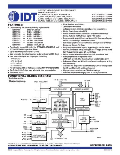
The IDT 72V series are high‑speed, high‑density FIFO memories that support flexible 9‑bit or 18‑bit bus widths and a range of programmable flags. They are intended for applications such as networking, video, and telecommunications where large data buffering and bus‑matching are required.
Key features include selectable synchronous or asynchronous operation, multiple timing modes (Standard and First‑Word‑Fall‑Through), programmable almost‑empty/full flags, zero‑latency retransmit, and JTAG boundary‑scan support. The devices are offered in 80‑pin TQFP or 100‑pin BGA packages and operate over an industrial temperature range.
| Operating voltage | 3.3 V |
|---|---|
| Temperature range | -40 °C to +85 °C |
| Maximum memory depth | 128 K × 9 bits |
| Bus width options | x9 or x18 |
| Package types | 80‑pin TQFP or 100‑pin BGA |
Partial Reset initializes the read and write pointers to the first memory location while keeping the existing timing mode, programming method, and flag settings unchanged.
Flags can be loaded serially using SEN and LD on each WCLK edge, or in parallel using WEN and LD on each WCLK edge.
During Master Reset, a LOW on RM selects zero‑latency retransmit timing; a HIGH selects normal latency retransmit.
The FIFO supports four bus‑matching modes: x18‑x18, x18‑x9, x9‑x18, and x9‑x9.