
IDT72T1845, IDT72T1855, IDT72T1865, IDT72T1875, IDT72T1885, IDT72T1895, IDT72T18105, IDT72T18115, IDT72T18125 are a series of high-performance synchronous FIFO chips with a working voltage of 2.5V. They can be selected for HSTL/LVTTL input and output, and support a 225MHz operating frequency.
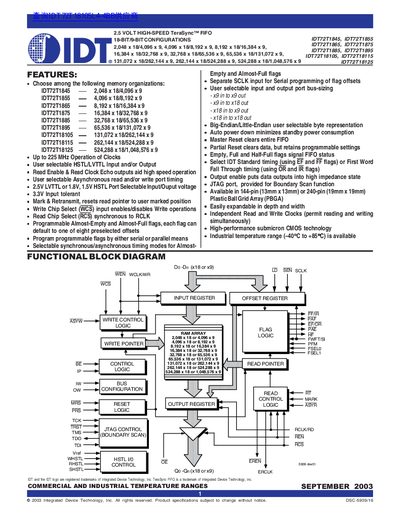
The TeraSync FIFO family from IDT offers deep, high‑speed CMOS memory with flexible bus‑matching (x18/x9) on both read and write ports. Users can select voltage standards (LVTTL or HSTL), endianness, and programmable flag thresholds for almost‑empty and almost‑full conditions.
The devices are available in 144‑pin (13 mm × 13 mm) or 240‑pin (19 mm × 19 mm) PBGA packages, operate up to 225 MHz, and support an industrial temperature range of –40 °C to +85 °C. Pin configurations, timing modes, and flag programming can be set via serial or parallel interfaces.
| Maximum clock frequency | Up to 225 MHz |
|---|---|
| Temperature range | -40 °C to +85 °C (industrial) |
| Package | 144‑pin (13 mm × 13 mm) or 240‑pin (19 mm × 19 mm) PBGA |
| Endianness | Big‑Endian or Little‑Endian selectable |
| Bus width options | x9 in to x9 out, x9 in to x18 out, x18 in to x9 out, x18 in to x18 out |
| Programmable flags | Almost‑Empty and Almost‑Full flags with up to eight offset settings |
The FIFO supports x9 or x18 input and output widths, selectable via the IW and OW pins (e.g., x9 in to x9 out, x9 in to x18 out).
Flags can be programmed with either serial (SEN and SCLK) or parallel (WEN and LD) methods, using up to eight predefined offset values.
The device can operate clocks up to 225 MHz.