
The AD800 and AD802 employ a second order phase-locked loop architecture to perform clock recovery and data retiming on Non-Return to Zero, NRZ, data. This architecture is capable of supporting data rates between 20 Mbps and 160 Mbps. The products described here have been defined to work with standard telecommunications bit rates. 45 Mbps DS-3 and 52 Mbps STS-1 are supported by the AD800-45 and AD800-52 respectively. 155 Mbps STS-3 or STM-1 are supported by the AD802-155. Unlike other PLL-based clock recovery circuits, these devices do not require a preamble or an external VCXO to lock onto input data. The circuit acquires frequency and phase lock using two control loops.
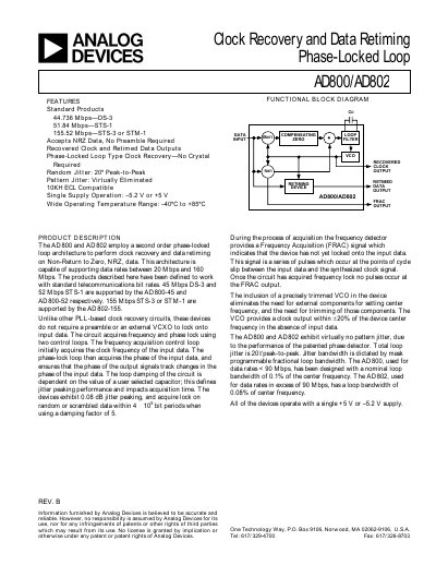
The AD800 and AD802 are second‑order phase‑locked loop devices that recover clock and retime data from non‑return‑to‑zero (NRZ) streams. They support standard telecom bit rates such as DS‑3 (45 Mbps), STS‑1 (52 Mbps) and STS‑3/STM‑1 (155 Mbps) without requiring a preamble or external VCXO.
Key features include single‑supply operation (‑5.2 V or +5 V), programmable loop damping via an external capacitor, low jitter (0.08 dB peak‑to‑peak), and wide temperature range (‑40 °C to +85 °C). The datasheet provides detailed specifications, pin descriptions, absolute maximum ratings, and recommended board layout and power‑supply practices.
| Center Frequency | 44.736 MHz (AD800‑45), 51.84 MHz (AD800‑52), 155.52 MHz (AD802‑155) |
|---|---|
| Supported Data Rate Range | 20 Mbps to 160 Mbps |
| Operating Temperature | ‑40 °C to +85 °C (B‑grade), 0 °C to +70 °C (R‑grade) |
| Power Supply Voltage | ‑5.2 V or +5 V (single supply) |
| Input Logic High Voltage | ‑1.084 V (‑5.2 V supply) or –0.72 V (‑5.2 V supply) |
| Output Jitter | 0.08 dB peak‑to‑peak |
| Loop Bandwidth | 0.1 % of center frequency (AD800), 0.08 % (AD802) |
| Capture Range | 43 Mbps to 49 Mbps (AD800‑45), 155 Mbps to 156 Mbps (AD802‑155) |
They support NRZ data rates from 20 Mbps up to 160 Mbps.
No, the PLLs lock onto input data without a preamble or external VCXO.
They operate from a single supply of either +5 V or –5.2 V.
During frequency acquisition the FRAC output pulses; when lock is achieved the FRAC output stops pulsing.