
This article introduces the architecture of Atmel PLD products and the timing calculation methods. It also mentions the tools and software packages that design engineers can use. Atmel PLDs have deterministic and path-independent delays, which greatly simplify timing calculation.
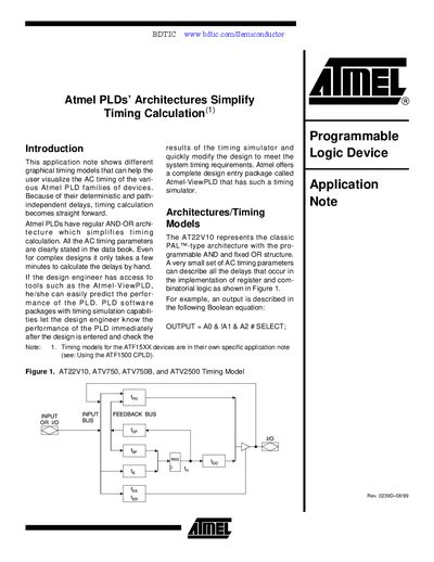
This application note explains how the regular AND‑OR architecture of Atmel PLDs simplifies timing calculation. It introduces graphical timing models that let designers visualize AC timing for devices such as the AT22V10, ATV750, ATV750B, ATV2500 and ATV2500B, and shows how to compute delays by hand or with Atmel‑ViewPLD tools.
The note also details the AC timing parameters (tpp, tpps, tppg, top, tepe, etc.), their meanings for combinatorial and registered paths, and provides example equations and tables for typical Mealy state‑machine implementations.
| tpp | delay from any pin to any combinatorial output |
|---|---|
| tpps | delay from internal feedback nodes to a combinatorial output pin |
| tepe | delay from a pin to a combinatorial output in a Mealy state machine |
Atmel PLDs use parameters such as tpp, tpps, tppg, top, tepe, and others to describe pin‑to‑pin, feedback, and combinatorial delays.
Yes, because the devices have deterministic, path‑independent delays, the AC timing parameters allow hand calculation of delays in a few minutes.