
This document describes the features and characteristics of the MITSUBISHI
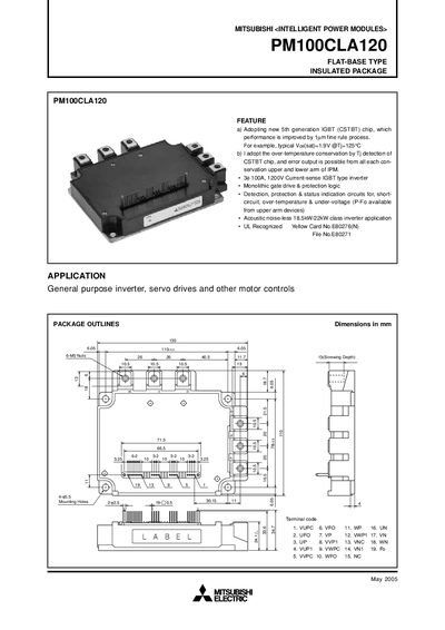
The PM100CLA120 is a flat‑base, insulated intelligent power module featuring a 5th‑generation IGBT (CSTBT) chip, 100 A continuous current and 1200 V rating for inverter and motor‑drive applications. It includes built‑in gate‑drive, protection and status circuits for short‑circuit, over‑temperature and under‑voltage detection.
The manual provides block diagrams, maximum electrical and mechanical ratings, testing precautions, performance curves and recommended wiring practices to ensure reliable and safe operation in industrial inverter systems.
| Collector‑Emitter Voltage (VCE(sat)) | 1.9 V @ Tj=125 °C |
|---|---|
| Continuous Collector Current | 100 A |
| Peak Collector Current | 200 A |
| Power Dissipation | 781 W |
| Junction Temperature Range | -20 °C to +150 °C |
| Supply Voltage (Control Part) | 13.5 V ~ 16.5 V |
| Surge Voltage | 1000 V |
| Mounting Torque (Main terminal screw) | 2.5 – 3.5 N·m |
| Weight | 800 g |
The typical VCE(sat) is 1.9 V measured at a junction temperature of 125 °C.
The module can continuously handle a collector current of 100 A.
A torque of 2.5 to 3.5 N·m is recommended for the M5 main terminal screw.
The IPM includes short‑circuit, over‑temperature, under‑voltage and fault‑output protection for each arm.