
This document describes the features of the Mitsubishi Intelligent Power Module PM200CLA060, released in May 2005. It includes the adoption of a new 5th generation IGBT chip, improved performance, and applications in general-purpose inverters, servo drives, and other motor control systems.
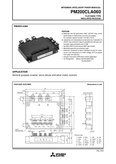
The PM200CLA060 is a flat‑base, insulated Intelligent Power Module featuring a 5th‑generation IGBT (CSTBT) chip, over‑temperature protection, and built‑in short‑circuit, over‑temperature and under‑voltage detection. It is intended for general‑purpose inverter, servo drive and motor‑control applications up to 22 kW.
The manual provides detailed electrical characteristics, mechanical ratings, recommended mounting and wiring practices, testing precautions, and performance curves to ensure safe and reliable operation of the module.
| Collector Current (continuous) | 200 A |
|---|---|
| Collector Current (peak) | 400 A |
| Collector‑Emitter Voltage | 600 V |
| Collector Dissipation | 781 W |
| Junction Temperature Range | -20 °C to +150 °C |
| Supply Voltage (operating) | 13.5 V ~ 16.5 V |
| Mounting Torque (main terminal screw) | 2.5 – 3.5 N·m |
| Mounting Torque (mounting part screw) | 2.5 – 3.5 N·m |
| Weight | 800 g |
The module is rated for a continuous collector current of 200 A.
It includes short‑circuit, over‑temperature, and under‑voltage detection with fault‑output signals for each arm of the IPM.
Both the main terminal screw and the mounting part screw should be tightened to 2.5 – 3.5 N·m.
Apply a supply voltage between 13.5 V and 16.5 V to the module.